Handling Description
Samsung Electronics
9-7
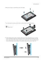
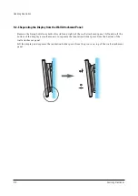
4. Remove four large screws from the rear side of the display.
5. nsert the bolts and insulations into the four screwholes as shown in the following figure:
Œ
Bolt
´
Insulation holder
6. Put the insulation rubber point protruding from the rear top of the display in the groove on the top
of the wall attachment panel. Lift up the display a little bit so that the insulation rubber point at the
bottom of the rear side of the display is put in the groove at the bottom of the wall attachment panel.
(Do not lift the display with any pressure. The insulation rubber at the top may be taken off. )
´
Œ
Содержание PPM42S2X/XAA
Страница 2: ...ELECTRONICS Samsung Electronics Co Ltd APR 2002 Printed in Korea AA82 ...
Страница 10: ...3 2 Samsung Electronics MENO ...
Страница 25: ...Circuit Operation Description Samsung Electronics 5 3 5 1 2 D PDP PS 42 BLOCK DIAGRAM ...
Страница 38: ...Circuit Operation Description 5 16 Samsung Electronics 5 2 3 D DRIVER CIRCUIT DIAGRAM ...
Страница 39: ...Circuit Operation Description Samsung Electronics 5 17 5 2 3 E DRIVER BOARD CONNECTOR LAYOUT ...
Страница 40: ...Circuit Operation Description 5 18 Samsung Electronics ...
Страница 41: ...Circuit Operation Description Samsung Electronics 5 19 ...
Страница 42: ...Circuit Operation Description 5 20 Samsung Electronics ...
Страница 43: ...Circuit Operation Description Samsung Electronics 5 21 ...
Страница 44: ...Circuit Operation Description 5 22 Samsung Electronics ...
Страница 45: ...Circuit Operation Description Samsung Electronics 5 23 ...
Страница 46: ...Circuit Operation Description 5 24 Samsung Electronics ...
Страница 47: ...Circuit Operation Description Samsung Electronics 5 25 ...
Страница 48: ...Circuit Operation Description 5 26 Samsung Electronics ...
Страница 49: ...Circuit Operation Description Samsung Electronics 5 27 ...
Страница 50: ...Circuit Operation Description 5 28 Samsung Electronics ...
Страница 51: ...Circuit Operation Description Samsung Electronics 5 29 ...
Страница 52: ...Circuit Operation Description 5 30 Samsung Electronics ...
Страница 53: ...Circuit Operation Description Samsung Electronics 5 31 5 3 Logic part 5 3 1 Logic Board Block diagram ...
Страница 76: ...Circuit Operation Description 5 54 Samsung Electronics 29 Jig board U1 LE01 pin35 30 Jig board U1 LE01 pin46 ...
Страница 77: ...Circuit Operation Description Samsung Electronics 5 55 31 Jig board U2 LE02 pin35 32 Jig board U2 LE02 pin46 ...
Страница 82: ...Circuit Operation Description 5 60 Samsung Electronics ...
Страница 83: ...Circuit Operation Description Samsung Electronics 5 61 ...
Страница 84: ...Circuit Operation Description 5 62 Samsung Electronics MEMO ...
Страница 93: ...Exploded View Parts List Samsung Electronics 7 1 7 Exploded View Parts List 7 1 PPM42S2X XAA ...
Страница 106: ...Electrical Parts List 8 12 Samsung Electronics MEMO ...
Страница 128: ...10 14 Samsung Electronics MEMO ...
Страница 130: ...11 2 Samsung Electronics MENO ...
Страница 133: ...Samsung Electronics Schematic Diagrams 12 3 TP01 12 3 SCALER3 3D COMB FILTER TP01 CVBS IN ...
Страница 134: ...Schematic Diagrams 12 4 Samsung Electronics 12 4 SCALER4 VIDEO DECODER PIP FIRST IN OUTPUT ...
Страница 135: ...Samsung Electronics Schematic Diagrams 12 5 12 5 SCALER5 VIDEO DA CON ...
Страница 137: ...Samsung Electronics Schematic Diagrams 12 7 12 7 SCALER7 ADC VIDEO TP20 TP21 TP19 TP19 HS OUT TP20 VHS TP21 VCLK ...
Страница 138: ...Schematic Diagrams 12 8 Samsung Electronics 12 8 SCALER8 ADC PC TP23 TP24 TP22 TP22 MHSYNC TP23 MHS TP24 PCLK ...
Страница 140: ...Schematic Diagrams 12 10 Samsung Electronics 12 10 SCALER10 POWER DEGUGER MEMORY REMOCON RS232 RTC ...
Страница 141: ...Samsung Electronics Schematic Diagrams 12 11 12 11 SOUND ...
Страница 143: ...Samsung Electronics Schematic Diagrams 12 13 12 13 CONTROL REMOCON CONTROL REMOCON ...


