73
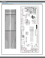
5. PCB Diagrams
5-2 PCB Diagrams (Sub)
(This Document can not be used without Samsung’s authorization)
ྙ
ྚ
ྛ
ྚ
ྜ
ྞ
ྜྷ
ྟ
ྠ
ྡྡྷ
No.
P
arts Number
Part Name
Function and Rule
1
CN01
Door plunger switch, cooktop warming center
,
oven lamp and relay of convection fan connector
This is connector which is connected with Door plunger switch and Door lock switch. (COM-NO, COM-NC)
2
CN04, CN05
R
elay connector
Connector(CN04,CN05) on sub PCB take a role of getting all of the operation of relay on sub PCB to co
nnect with main PCB(CN04,CN05).
3
DLB relay(Ry02)
DLB Relay
Circuit is designed to have broil relay or convection relay worked after DLB relay is being worked by Double line break. (It wi
ll not be problem
with reversing the order in insering Orange and Red)
4
Broil relay(Ry03)
Broil relay
Broil relay(Ry03), Bake relay(Ry04), convection relay(Ry05) will be on-of
f working by micom signal
after DLB relay is worked.
(Broil relay : It will not be problem with reversing the order in insering Black and Brown)
(Bake relay : It will not be problem with reversing the order in insering
Y
ellow and Gray)
5
B
ake relay(Ry04)
Bake relay
6
Convection relay(Ry05)
Convection relay
7
R
Y
-source relay(Ry01)
Source relay
This is consisted of 15 pin and take a role of getting a cable on keypad to connect with touc
h PCB.
8
:'UDZHU5HOD\5\DQG
T03 terminal
W
a
rmer drawer terminal & W
a
rmer drawer relay
This is terminal to connect harness with relay to get heater on warming drawer work
.
9
T
02 terminal
Convection terminal
This is the terminal to connect convection heater with convection relay
.
10
T01 terminal
Live 1
T
e
rminal
T
his is the terminal to supply L1 voltage(120V) with warming drawer relay(Ry06),convection relay(R
y05).


