10 Operating Installations and Installation
10-1
10 Operating Installations and Installation
10-1 Product Features
10-1-1 Front
1. SOURCE
Displays a menu of all of the available input
sources(TV - AV1 - AV2 - S-Video - PC).
You can also use the SOURCE( )button on the
TV's control panel to make selections.
2. MENU
Press to see an on-screen menu of your TV's
features.
3. - +
Moves the selector left or right on the OSD.
Decreases or increases the level of audio
volume and the values of the selected function.
4.
Moves the selector down or up on the OSD.
Decreases or increases the channel number.
5. POWER
Turns ON/OFF your set.
6. HEADPHONE
7. SPEAKERS
8. REMOTE CONTROL SENSOR
Aims the remote control towards this spot on the
TV.
9. POWER INDICATOR
Lights up when you turn the power off.
(Red light shows in stand-by mode, Red shows
when you turn the power on, and light is off after
the power is on. Green shows when you set
Timer on or off.)
Содержание LW15M23CP
Страница 6: ...Memo 1 Precautions 1 4 ...
Страница 23: ...4 Troubleshooting 4 3 WAVEFORMS 1 2 5 3 6 4 4 7 8 ...
Страница 26: ...4 Troubleshooting 4 6 Memo ...
Страница 29: ...5 Exploded View Parts List 5 3 5 2 LW17M24CP T0003 M0215 T0447 M0147 M0003 M0014 M0013 ...
Страница 31: ...5 Exploded View Parts List 5 5 5 3 LW20M21CP T0003 M0215 M0147 M0014 M0013 M0014 ...
Страница 63: ...7 Block Diagrams 7 1 7 Block Diagram ...
Страница 64: ...Memo 7 Block Diagrams 7 2 ...
Страница 66: ...8 Wiring Diagrams 8 2 Memo ...
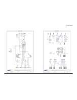
Страница 68: ...9 Schematic Diagrams 9 2 1 2 5 3 6 4 7 8 ...
Страница 70: ...9 Schematic Diagrams 9 4 9 ...
Страница 73: ...9 Schematic Diagrams 9 7 ...
Страница 74: ...9 Schematic Diagrams 9 8 ...
Страница 76: ...9 Schematic Diagrams 9 10 ...
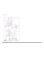
Страница 78: ...9 Schematic Diagrams 9 2 1 2 5 3 6 4 7 8 ...
Страница 80: ...9 Schematic Diagrams 9 4 9 ...
Страница 83: ...9 Schematic Diagrams 9 7 ...
Страница 84: ...9 Schematic Diagrams 9 8 ...
Страница 86: ...9 Schematic Diagrams 9 10 ...
Страница 88: ...9 Schematic Diagrams 9 2 1 2 5 3 6 4 7 8 ...
Страница 90: ...9 Schematic Diagrams 9 4 9 ...
Страница 93: ...9 Schematic Diagrams 9 7 ...
Страница 94: ...9 Schematic Diagrams 9 8 ...
Страница 96: ...9 Schematic Diagrams 9 10 ...
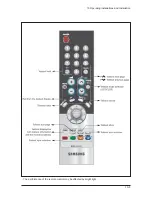
Страница 101: ...10 Operating Installations and Installation 10 5 The performance of the remote control may be affected by bright light ...
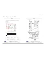
Страница 126: ...12 PCB Layout 12 2 12 1 2 Power board LW15M23CP ...
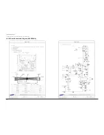
Страница 127: ...12 PCB Layout 12 3 12 1 2 Power board LW17M24CP LW20M21CP ...
Страница 128: ...12 PCB Layout 12 4 Memo ...
Страница 129: ...13 Circuit Descriptions 13 1 13 Circuit Descriptions 13 1 Overall Block Structure ...
Страница 130: ...13 Circuit Descriptions 13 2 13 2 1 MAIN BOARD POWER TREE 13 2 Partial Block Description ...
Страница 132: ...13 Circuit Descriptions 13 4 ...
Страница 133: ...13 Circuit Descriptions 13 1 13 Circuit Descriptions 13 1 Overall Block Structure ...
Страница 134: ...13 Circuit Descriptions 13 2 13 2 1 MAIN BOARD POWER TREE 13 2 Partial Block Description ...
Страница 136: ...13 Circuit Descriptions 13 4 ...

