10 Operating Installations and Installation
10-8
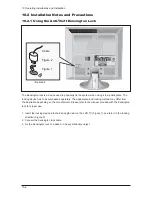
10-2-3 Installing VESA compliant mounting devices
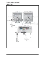
SCART
SCART
SCART
<1>
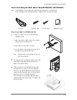
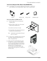
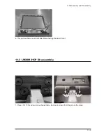
Fold the stand pressing the button on the back of the stand.
<2>
Align the mounting interface pad with the holes in the stand bottom and secure it with the four
screws that come with the arm-type base, wall mount hanger or other bases.
Wall Mount Instructions
The following instructions apply to a hollow sheet-rock wall only. Tools/Hardware needed - Philips
screwdriver, four toggle bolts, 5/8in dia. Drill bit and drill. Contact Ergotron at (800) 888-8458 to
purchase the triple pivot direct mount adapter and wall mount bracket kit.
- LW15M23CP (15") : No. 47 - 007 - 099 (Pivot direct mount adapter)
No. 97 - 101 - 003 (Wall mount bracket kit)
- LW17M24CP (17") : No. 47 - 007 - 099 (Pivot direct mount adapter)
No. 97 - 101 - 003 (Wall mount bracket kit)
- LW20M21CP (20") : No. 47 - 007 - 099 (Pivot direct mount adapter)
No. 97 - 101 - 003 (Wall mount bracket kit)
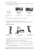
Align the wall mount bracket on the wall at the desired height, making sure that the bracket will be
mounted between the wall studs. Mark the four corner openings and drill four 5/8-diameter holes.
Assemble the wall mount kit according to the instructions provided with it. Securely attach Ergotron's
flat panel, triple pivot direct mount adapter to the back of the TV using the four 4mm,
0.7 pitch x 10mm screws provided with the arm. Secure the assembly to the wall using four 3/16 by
3-inch long toggle bolts.
1
2
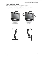
Mounting pad
LW15M23CP, LW17M24CP
LW20M21CP
Содержание LW15M23CP
Страница 6: ...Memo 1 Precautions 1 4 ...
Страница 23: ...4 Troubleshooting 4 3 WAVEFORMS 1 2 5 3 6 4 4 7 8 ...
Страница 26: ...4 Troubleshooting 4 6 Memo ...
Страница 29: ...5 Exploded View Parts List 5 3 5 2 LW17M24CP T0003 M0215 T0447 M0147 M0003 M0014 M0013 ...
Страница 31: ...5 Exploded View Parts List 5 5 5 3 LW20M21CP T0003 M0215 M0147 M0014 M0013 M0014 ...
Страница 63: ...7 Block Diagrams 7 1 7 Block Diagram ...
Страница 64: ...Memo 7 Block Diagrams 7 2 ...
Страница 66: ...8 Wiring Diagrams 8 2 Memo ...
Страница 68: ...9 Schematic Diagrams 9 2 1 2 5 3 6 4 7 8 ...
Страница 70: ...9 Schematic Diagrams 9 4 9 ...
Страница 73: ...9 Schematic Diagrams 9 7 ...
Страница 74: ...9 Schematic Diagrams 9 8 ...
Страница 76: ...9 Schematic Diagrams 9 10 ...
Страница 78: ...9 Schematic Diagrams 9 2 1 2 5 3 6 4 7 8 ...
Страница 80: ...9 Schematic Diagrams 9 4 9 ...
Страница 83: ...9 Schematic Diagrams 9 7 ...
Страница 84: ...9 Schematic Diagrams 9 8 ...
Страница 86: ...9 Schematic Diagrams 9 10 ...
Страница 88: ...9 Schematic Diagrams 9 2 1 2 5 3 6 4 7 8 ...
Страница 90: ...9 Schematic Diagrams 9 4 9 ...
Страница 93: ...9 Schematic Diagrams 9 7 ...
Страница 94: ...9 Schematic Diagrams 9 8 ...
Страница 96: ...9 Schematic Diagrams 9 10 ...
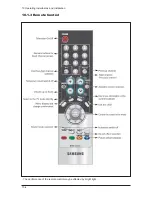
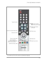
Страница 101: ...10 Operating Installations and Installation 10 5 The performance of the remote control may be affected by bright light ...
Страница 126: ...12 PCB Layout 12 2 12 1 2 Power board LW15M23CP ...
Страница 127: ...12 PCB Layout 12 3 12 1 2 Power board LW17M24CP LW20M21CP ...
Страница 128: ...12 PCB Layout 12 4 Memo ...
Страница 129: ...13 Circuit Descriptions 13 1 13 Circuit Descriptions 13 1 Overall Block Structure ...
Страница 130: ...13 Circuit Descriptions 13 2 13 2 1 MAIN BOARD POWER TREE 13 2 Partial Block Description ...
Страница 132: ...13 Circuit Descriptions 13 4 ...
Страница 133: ...13 Circuit Descriptions 13 1 13 Circuit Descriptions 13 1 Overall Block Structure ...
Страница 134: ...13 Circuit Descriptions 13 2 13 2 1 MAIN BOARD POWER TREE 13 2 Partial Block Description ...
Страница 136: ...13 Circuit Descriptions 13 4 ...


