10 Operating Installations and Installation
10-3
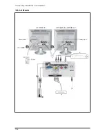
1. Connecting an Aerial or Cable Television Network (depending on the model)
To view television channels correctly, a signal must be received by the set from one of the
following sources:
- An outdoor aerial
- Acable television network
- Asatellite network
2. Connecting a Set-Top Box, VCR or DVD
- Connect the VCR, or DVD SCART cable to the SCART connector of the VCR, or DVD.
- If you wish to connect both the Set-Top Box and VCR (or DVD), you should connect the
Set-Top Box to the VCR (or DVD) and connect the VCR (or DVD) to your set.
3. Connecting a Computer
- Connect the 15 Pin D-SUB connector to the PC video connector.
- Connect the stereo audio cable to the "PC AUDIO IN STEREO" jack ( 7 )on the rear of your set
and the other end to the "Audio Out" jack of the sound card on your computer.
4. Connecting External A/V Devices
- Connect RCA or S-VIDEO cables to an appropriate external A/V device such as a VCR, DVD
or Camcorder.
- Connect RCA audio cables to "(MONO)L-AUDIO-R" on the rear of your set and the other ends
to corresponding audio out connectors on the A/V device.
5. Connecting Headphones
- Plug a set of headphones into the 3.5mm mini-jack socket on the right-side of the set.
While the headphones are connected, the sound from the built-in speakers will be disabled.
6. Kensington Slot
- This television has been designed to apply a burglarproof lock.
Содержание LW15M23CP
Страница 6: ...Memo 1 Precautions 1 4 ...
Страница 23: ...4 Troubleshooting 4 3 WAVEFORMS 1 2 5 3 6 4 4 7 8 ...
Страница 26: ...4 Troubleshooting 4 6 Memo ...
Страница 29: ...5 Exploded View Parts List 5 3 5 2 LW17M24CP T0003 M0215 T0447 M0147 M0003 M0014 M0013 ...
Страница 31: ...5 Exploded View Parts List 5 5 5 3 LW20M21CP T0003 M0215 M0147 M0014 M0013 M0014 ...
Страница 63: ...7 Block Diagrams 7 1 7 Block Diagram ...
Страница 64: ...Memo 7 Block Diagrams 7 2 ...
Страница 66: ...8 Wiring Diagrams 8 2 Memo ...
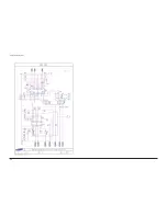
Страница 68: ...9 Schematic Diagrams 9 2 1 2 5 3 6 4 7 8 ...
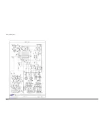
Страница 70: ...9 Schematic Diagrams 9 4 9 ...
Страница 73: ...9 Schematic Diagrams 9 7 ...
Страница 74: ...9 Schematic Diagrams 9 8 ...
Страница 76: ...9 Schematic Diagrams 9 10 ...
Страница 78: ...9 Schematic Diagrams 9 2 1 2 5 3 6 4 7 8 ...
Страница 80: ...9 Schematic Diagrams 9 4 9 ...
Страница 83: ...9 Schematic Diagrams 9 7 ...
Страница 84: ...9 Schematic Diagrams 9 8 ...
Страница 86: ...9 Schematic Diagrams 9 10 ...
Страница 88: ...9 Schematic Diagrams 9 2 1 2 5 3 6 4 7 8 ...
Страница 90: ...9 Schematic Diagrams 9 4 9 ...
Страница 93: ...9 Schematic Diagrams 9 7 ...
Страница 94: ...9 Schematic Diagrams 9 8 ...
Страница 96: ...9 Schematic Diagrams 9 10 ...
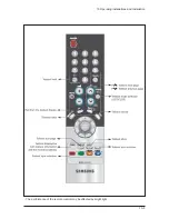
Страница 101: ...10 Operating Installations and Installation 10 5 The performance of the remote control may be affected by bright light ...
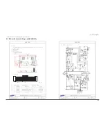
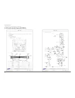
Страница 126: ...12 PCB Layout 12 2 12 1 2 Power board LW15M23CP ...
Страница 127: ...12 PCB Layout 12 3 12 1 2 Power board LW17M24CP LW20M21CP ...
Страница 128: ...12 PCB Layout 12 4 Memo ...
Страница 129: ...13 Circuit Descriptions 13 1 13 Circuit Descriptions 13 1 Overall Block Structure ...
Страница 130: ...13 Circuit Descriptions 13 2 13 2 1 MAIN BOARD POWER TREE 13 2 Partial Block Description ...
Страница 132: ...13 Circuit Descriptions 13 4 ...
Страница 133: ...13 Circuit Descriptions 13 1 13 Circuit Descriptions 13 1 Overall Block Structure ...
Страница 134: ...13 Circuit Descriptions 13 2 13 2 1 MAIN BOARD POWER TREE 13 2 Partial Block Description ...
Страница 136: ...13 Circuit Descriptions 13 4 ...

