14 Reference Infomation
14-5
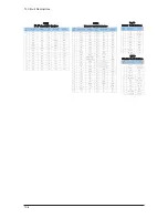
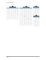
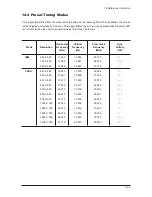
14-4 Preset Timing Modes
If the signal transferred from the computer is the same as the following Preset Timing Modes, the screen
will be adjusted automatically. However, if the signal differs, the screen may go blank while the power LED
is on. Refer to the video card manual and adjust the screen as follows.
IBM
640 X 350
31.469
70.086
25.175
+ / -
720 X 400
31.469
70.087
28.322
- / +
640 X 480
31.469
59.940
25.175
- / -
VESA
640 X 480
35.000
70.000
28.560
- / -
640 X 480
37.861
72.809
31.500
- / -
640 X 480
37.500
75.000
31.500
- / -
800 X 600
37.879
60.317
40.000
+ / +
800 X 600
48.077
72.188
50.000
+ / +
800 X 600
46.875
75.000
49.500
+ / +
800 X 600
43.750
70.000
45.500
- / -
1024 X 768
48.363
60.004
65.000
- / -
1024 X 768
56.476
70.069
75.000
- / -
1024 X 768
56.672
72.000
78.434
- / -
1024 X 768
60.023
75.029
78.750
+ / +
1360 X 768
47.712
60.015
85.800
+ / +
Mode
Resolution
Horizontal
Frequency
(kHz)
Vertical
Frequency
(Hz)
Pixel Clock
Frequency
(MHz)
Sync
Polarity
(H/V)
Содержание LW15M23CP
Страница 6: ...Memo 1 Precautions 1 4 ...
Страница 23: ...4 Troubleshooting 4 3 WAVEFORMS 1 2 5 3 6 4 4 7 8 ...
Страница 26: ...4 Troubleshooting 4 6 Memo ...
Страница 29: ...5 Exploded View Parts List 5 3 5 2 LW17M24CP T0003 M0215 T0447 M0147 M0003 M0014 M0013 ...
Страница 31: ...5 Exploded View Parts List 5 5 5 3 LW20M21CP T0003 M0215 M0147 M0014 M0013 M0014 ...
Страница 63: ...7 Block Diagrams 7 1 7 Block Diagram ...
Страница 64: ...Memo 7 Block Diagrams 7 2 ...
Страница 66: ...8 Wiring Diagrams 8 2 Memo ...
Страница 68: ...9 Schematic Diagrams 9 2 1 2 5 3 6 4 7 8 ...
Страница 70: ...9 Schematic Diagrams 9 4 9 ...
Страница 73: ...9 Schematic Diagrams 9 7 ...
Страница 74: ...9 Schematic Diagrams 9 8 ...
Страница 76: ...9 Schematic Diagrams 9 10 ...
Страница 78: ...9 Schematic Diagrams 9 2 1 2 5 3 6 4 7 8 ...
Страница 80: ...9 Schematic Diagrams 9 4 9 ...
Страница 83: ...9 Schematic Diagrams 9 7 ...
Страница 84: ...9 Schematic Diagrams 9 8 ...
Страница 86: ...9 Schematic Diagrams 9 10 ...
Страница 88: ...9 Schematic Diagrams 9 2 1 2 5 3 6 4 7 8 ...
Страница 90: ...9 Schematic Diagrams 9 4 9 ...
Страница 93: ...9 Schematic Diagrams 9 7 ...
Страница 94: ...9 Schematic Diagrams 9 8 ...
Страница 96: ...9 Schematic Diagrams 9 10 ...
Страница 101: ...10 Operating Installations and Installation 10 5 The performance of the remote control may be affected by bright light ...
Страница 126: ...12 PCB Layout 12 2 12 1 2 Power board LW15M23CP ...
Страница 127: ...12 PCB Layout 12 3 12 1 2 Power board LW17M24CP LW20M21CP ...
Страница 128: ...12 PCB Layout 12 4 Memo ...
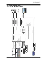
Страница 129: ...13 Circuit Descriptions 13 1 13 Circuit Descriptions 13 1 Overall Block Structure ...
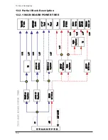
Страница 130: ...13 Circuit Descriptions 13 2 13 2 1 MAIN BOARD POWER TREE 13 2 Partial Block Description ...
Страница 132: ...13 Circuit Descriptions 13 4 ...
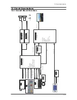
Страница 133: ...13 Circuit Descriptions 13 1 13 Circuit Descriptions 13 1 Overall Block Structure ...
Страница 134: ...13 Circuit Descriptions 13 2 13 2 1 MAIN BOARD POWER TREE 13 2 Partial Block Description ...
Страница 136: ...13 Circuit Descriptions 13 4 ...


