background image

Disassembly and Reassembly

1-6

Samsung Electronics

1-2-2 Diassembly

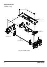
2  SCREWS

UPPER CHASSIS

CHASSIS SIDE "R"

HOLDER

CASSETTE ASS'Y

SHAFT ARM ASS'Y

CHASSIS SIDE "L"

Fig. 1-6 Housing Ass’y Removal

Содержание DX7-A

Страница 1: ...DX7 A DX7 AC DX8 A DX8 AC 1 Disassembly and Reassembly 2 Alignment and Adjustment VHS DECK CONTENTS MECHANICALManual 3 File with the SERVICE MANUAL Samsung Electronics Co Ltd NOV 1997 AC68 20392A ...

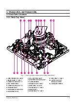
Страница 2: ...MAIN L ASS Y 3 GUIDE ROLLER ASS Y T 4 FULL ERASE HEAD 5 GUIDE ROLLER ASS Y S 6 CYLINDER ASS Y 7 LEVER PINCH COMP ASS Y 8 LEVER PINCH CAM 9 FULL ACE HEAD AAS Y 10 UNIT PINCH ROLLER ASS Y 11 LEVER REVIEW 12 BRAKE SUB R ASS Y 13 REEL DISK R ASS Y 14 GEAR RELAY T ASS Y 15 IDLER ASS Y 16 GEAR RELAY S ASS Y 17 REEL DISK L ASS Y 18 LEVER JOG ASS Y DX8 A AC ONLY 19 LEVER REC SWITCH 1 Disassembly and Reass...

Страница 3: ...IN L ASS Y 3 GUIDE ROLLER ASS Y T 4 FULL ERASE HEAD 5 HEAD CLEANER ASS Y DX7 AC DX8 AC ONLY 6 GUIDE ROLLER ASS Y S 7 CYLINDER ASS Y 8 LEVER PINCH COMP ASS Y 9 LEVER PINCH CAM 10 FULL ACE HEAD AAS Y 11 UNIT PINCH ROLLER ASS Y 12 LEVER REVIEW 13 BRAKE SUB R ASS Y 14 REEL DISK R ASS Y 15 GEAR RELAY T ASS Y 16 IDLER ASS Y 17 GEAR RELAY S ASS Y 18 REEL DISK L ASS Y 19 LEVER JOG ASS Y DX8 A AC ONLY 20 L...

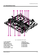
Страница 4: ... 9 10 11 13 12 Fig 1 3 Deck Bottom Parts Location 1 LEVER SLIDE PINCH 2 BELT CAPSTAN 3 MOTOR D D CAPSTAN 4 BRAKE CAPSTAN ASS Y 5 GEAR LOADING R ASS Y 6 MOTOR CYLINDER 7 GEAR LOADING L ASS Y 8 SLIDE MAIN 9 LEVER REC SWITCH 10 LEVER IDLER CHANGE 11 CLUTCH ASS Y 12 UNIT LOADING 13 GEAR MASTER ...

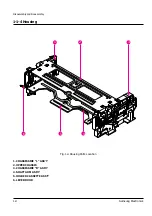
Страница 5: ... and Reassembly 1 4 Samsung Electronics 1 1 4 Housing 1 2 3 4 6 5 Fig 1 4 Housing Parts Location 1 CHASSIS SIDE L ASS Y 2 UPPER CHASSIS 3 CHASSIS SIDE R ASS Y 4 SHAFT ARM ASS Y 5 HOLDER CASSETTE ASS Y 6 LEVER DOOR ...

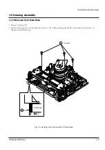
Страница 6: ...g Assembly 1 2 1 Removal from Main Base 1 Remove 3 Screws 2 Lift the Housing AssÕy in the direction of arrow ÒBÓ while pushing the tab in the direction of arrow ÒAÓ Refer to detail drawing 3 SCREWS 1 MAIN BASE TAB A 2 Fig 1 5 Housing Ass y Removal from Main Base ...

Страница 7: ...Disassembly and Reassembly 1 6 Samsung Electronics 1 2 2 Diassembly 2 SCREWS UPPER CHASSIS CHASSIS SIDE R HOLDER CASSETTE ASS Y SHAFT ARM ASS Y CHASSIS SIDE L Fig 1 6 Housing Ass y Removal ...

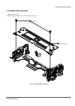
Страница 8: ...ssembly and Reassembly Samsung Electronics 1 7 1 2 3 Upper Chassis Removal 1 Remove 2 Screws 2 Lift the Upper Chassis in the direction of arrow ÒAÓ 2 SCREWS UPPER CHASSIS 2 A 1 Fig 1 7 Upper Chassis Removal ...

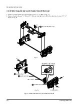
Страница 9: ...ow ÒAÓ Refer to Fig A 2 Remove the Side Chassis ÒLÓ and ÒRÓ from Arm Shaft AssÕy in the direction of arrow ÒBÓ ÒCÓ Refer to Fig B HOLDER CASSETTE ASS Y A 1 2 4 SHAFT ARM ASS Y CHASSIS SIDE L 3 CHASSIS SIDE R SLIDE DAMPER B Fig A Fig B DETAIL REASSEMBLY OF CHASSIS SIDE R SHAFT ARM R SIDE VIEW C D SHAFT ARM R Fig 1 8 Holder Cassette Ass y and Chassis Side L R ...

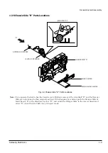
Страница 10: ...9 Chassis Side R Parts Locations Note If you operate the deck when the Cassette AssÕy Holder is removed the Arm Shaft ÒRÓ and the Damper Slide are not returned to their original positions If this happens by accident push the Damper Slide of Side Chassis ÒRÓ in the direction of arrow ÒDÓ and return the Damper Slide in the reverse direction of arrow ÒDÓ when the Arm Shaft AssÕy is in eject mode ...

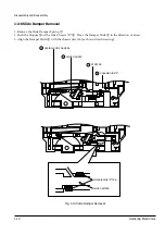
Страница 11: ...per Spring 2 Push the Stopper of the Side Chassis ÒRÓ Move the Damper Slide in the direction of arrow 3 Align the Damper Slide with the chassis side tab as shown detail drawing CHASSIS SIDE R CHASSIS SIDE R TAB SLIDE DAMPER 4 STOPPER 3 SLIDE DAMPER 2 SPRING SLIDE DAMPER 1 Fig 1 10 Slide Damper Removal ...

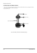
Страница 12: ... Electronics 1 11 1 3 Cylinder Ass y 1 3 1 Exploded View of Cylinder Ass y ASS Y MOTOR ROTOR ASS Y SUB CYLINDER 2 SCREWS 3 SCREWS 2 SCREWS ASS Y MOTOR STATOR ASS Y BASE CYLINDER SPRING CARBON TIP Fig 1 11 Expleded View of Cylinder Ass y ...

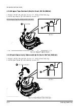
Страница 13: ...er in the direction of arrow ÒBÓ B TAB DETAIL A 1 STOPPER TAPE 2 Fig 1 12 Stopper Tape Removal 1 3 3 Head Cleaner Ass y Removal Only for Deck DX7 AC DX8 AC 1 Release 1 tab in the direction of arrow ÒAÓ Refer to detail drawing 2 Lift the Head Cleaner in the direction of arrow ÒBÓ ASS Y HEAD CLEANER B 2 TAB DETAIL A 1 Fig 1 13 Head Cleaner Ass y Removal Note Stopper tape has deleted from JAN 1998 ...

Страница 14: ...emoval from Main Base 1 Remove 3 Screws holding the Main Base and the Cylinder AssÕy 2 Lift the Cylinder AssÕy in the direction of arrow Note Do not touch the video heads during removal or installation 3 SCREWS 1 CYLINDER ASS Y 2 Fig 1 14 Cylinder Ass y Removal from Main Base ...

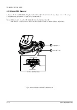
Страница 15: ...of arrow Refer to detail drawing 2 Disconnect the Holder FPC from the Cylinder Base Note When disconnecting the FPC Holder from the Cylinder Base Take care not to disconnect the FPC cable from the FPC Holder The FPC cable is very short HOLDER FPC CYLINDER BASE CYLINDER BASE HOLDER FPC DETAIL BOTTOM VIEW 2 1 Fig 1 15 Head Brush and Holder FPC Removal ...

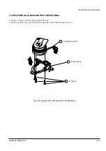
Страница 16: ...6 Cylinder Ass y Removal from Cylinder Base 1 Remove 3 Screws from the Cylinder Base 2 Lift the Cylinder AssÕy from the Cylinder Base in the direction of arrow CYLINDER SUB ASS Y CYLINDER BASE 3 SCREWS 2 1 3 Fig 1 16 Cylinder Ass y Removal from Cylinder Base ...

Страница 17: ...emoval 1 Remove 2 Screws 2 Remove the Motor Stator from the Cylinder Sub AssÕy MOTOR STATOR CYLINDER SUB ASS Y 2 2SCREWS 1 5 SPRING CARBON TIP 3 4 Fig 1 17 Motor Stator Removal Note When disassembling the Motor Stator take extreme care not to loose the carbon tip and spring ...

Страница 18: ...Disassembly and Reassembly Samsung Electronics 1 17 1 3 8 Motor Rotor Removal 1 Remove 2 Screws 2 Lift The Motor Rotor MOTOR ROTOR DRUM SUB ASS Y 2 3 2 SCREWS 1 Fig 1 18 Motor Rotor Removal ...

Страница 19: ... Make sure that phase matching holes of the Motor Rotor and the Cylinder Sub AssÕy are aligned correctly as shown in Fig 1 19 Refer to phase matching hole 2 Secure with 2 Screws MOTOR ROTOR PHASE MATCHING HOLE DRUM SUB ASS Y 2 3 2 SCREWS 1 Fig 1 19 Assembly of Motor Rotor and Cylinder Sub Ass y ...

Страница 20: ...1 19 1 3 10 Motor Stator and Cylinder Sub Ass y 1 Reinstall the Motor Stator toward the FPC cable of Cylinder Sub AssÕy 2 Secure 2 Screws Refer to Fig 1 17 MOTOR STATOR CYLINDER SUB ASS Y 1 2 Fig 1 20 Assembly of Motor Stator and Cylinder Sub Ass y ...

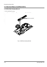
Страница 21: ...sassembly and Reassembly 1 20 Samsung Electronics 1 4 Main Deck Removal and Reassembly 1 4 1 Slide Rack Housing Removal 1 Lift the Slide Rack Housing SLIDE RACK HOUSING Fig 1 21 Slide Rack Housing Removal ...

Страница 22: ...Master Gear and the hole ÒAÓ of Main Base are aligned correctly Eject mode 2 Align the Slot 1 of Master Gear with the Tooth 1 of Rack Housing Slide Refer to timing point SLIDE VIEW DETAIL A TIMING POINT SLOT 1 TOOTH 1 GEAR MASTER TOP VIEW SIDE VIEW 1 SLIDER RACK HOUSING ARM R 2 Fig 1 22 Assembly of Slide Rack Housing and Gear Master ...

Страница 23: ...nics 1 4 3 Brake Sub L Removal 1 Remove the Sub ÒLÓ Brake Spring 2 Release the tab in the direction of arrow Refer to detail drawing 3 Lift the Sub ÒLÓ Brake DETAIL BRAKE SUB L 3 TAB 2 SPRING BRAKE SUB L 1 BRAKE SUB L 3 Fig 1 23 Brake Sub L Removal ...

Страница 24: ...n Full Ass y Removal 1 Remove the Tension Spring 2 Release the tab in the direction of arrow Refer to detail drawing 3 Lift the Full Tension Arm AssÕy DETAIL SPRING TENSION 1 ARM TENSION FULL ASS Y 3 TAB 2 ARM TENSION FULL ASS Y 3 Fig 1 24 Arm Tension Full Ass y Removal ...

Страница 25: ...ly 1 24 Samsung Electronics 1 4 5 Lever JOG Ass y Removal Only for deck DX8 A DX8 AC 1 Remove the 1 Screw 2 Lift the JOG Lever AssÕy TOP VIEW 1 SCREW 1 LEVER JOG ASS Y LEVER JOG ASS Y 2 TIMING Fig 1 25 Lever JOG Ass y Removal ...

Страница 26: ...tail drawing 2 Lift the Reel Disk ÒLÓ 3 Remove the Plain Washer 4 Remove the Slit Washer 5 Lift the Relay ÒSÓ Gear AssÕy Note When reinstalling be sure to install the Reel Disk ÒLÓ after installing the Plain Washer DETAIL REEL DISK L 2 TAB 1 WASHER PLAIN 3 REEL DISK L 2 WASHER SLIT 4 GEAR RELAY S ASS Y 5 Fig 1 26 Reel Disk L and Gear Relay S Ass y Removal ...

Страница 27: ...e Sub R Ass y Removal 1 Remove the Sub ÒRÓ Brake Spring 2 Release the tab in the direction of arrow Refer to detail drawing 3 Lift the Brake Sub ÒRÓ AssÕy SPRING BRAKE SUB R 1 BRAKE SUB R ASS Y 3 BRAKE SUB R ASS Y DETAIL 3 TAB 2 Fig 1 27 Brake Sub R Ass y Removal ...

Страница 28: ...ing 2 Lift the Reel Disk ÒRÓ AssÕy 3 Remove the Plain Washer 4 Remove the Slit Washer 5 Lift the Relay ÒTÓ Gear AssÕy Note When reinstalling be sure to install the Reel Disk ÒRÓ AssÕy after installing the Plain Washer REEL DISK R ASS Y DETAIL 2 TAB 1 REEL DISK R ASS Y 2 WASHER PLAIN 3 GEAR RELAY T 5 WASHER SLIT 4 Fig 1 28 Reel Disk R Ass y and Gear Relay T Removal ...

Страница 29: ...rection of arrow ÒAÓ Refer to detail drawing A 3 Lift the Brake Main ÒLÓ 4 Release the tab in the direction of arrow ÒBÓ Refer to detail drawing B 5 Lift the Main ÒRÓ Brake BRAKE MAIN R ASS Y 5 BRAKE MAIN L ASS Y DETAIL A DETAIL B 3 TAB A B 2 BRAKE MAIN R ASS Y 5 TAB 4 BRAKE MAIN L ASS Y 3 SPRING BRAKE MAIN 1 Fig 1 29 Brake Main L R Ass y Removal ...

Страница 30: ...Disassembly and Reassembly Samsung Electronics 1 29 1 4 10 Idler Ass y Removal 1 Remove the Slit Washer 2 Lift the Idler AssÕy IDLER ASS Y 2 WASHER SLIT 1 Fig 1 30 Idler Ass y Removal ...

Страница 31: ...Samsung Electronics 1 4 11 Unit Pinch Roller Ass y Removal 1 Remove the Slit Washer 2 Lift the Pinch Roller Unit 3 Lift the Arm Pinch Spring UNIT PINCH ROLLER 2 WASHER SLIT 1 SPRING ARM PINCH 3 Fig 1 31 Unit Pinch Roller Ass y Removal ...

Страница 32: ...g Electronics 1 31 1 4 12 Assembly of Unit Pinch Roller 1 Install the Pinch Roller Unit as shown in Fig 1 32 Refer to A B MOTOR D D CAPSTAN UNIT PINCH ROLLER SLIDER PINCH TOP VIEW B SLIDER PUSH A Fig 1 32 Assembly of Unit Pinch Roller ...

Страница 33: ...oded View of Lever Pinch Comp Ass y Lever Pinch Cam Arm Review Ass y and Lever Review Ass y LEVER PINCH COMP ASS Y LEVER PINCH CAM ARM REVIEW ASS Y LEVER REVIEW Fig 1 33 Exploded View of Lever Pinch Comp Ass y Lever Pinch Cam Arm Review Ass y and Lever Review Ass y ...

Страница 34: ...oval 1 Release the tab in the direction of arrow Refer to detail drawing 2 Lift the Pinch Comp Lever AssÕy Note DonÕt touch the Pinch Comp Lever AssÕy to Audio Head Base during removal LEVER PINCH COMP ASS Y 2 LEVER PINCH COMP ASS Y 2 TAB DETAIL 1 Fig 1 34 Lever Pinch Comp Ass y Removal ...

Страница 35: ...34 Samsung Electronics 1 4 15 Lever Pinch Cam Removal 1 Release the tab in the direction of arrow Refer to detail drawing 2 Lift the Pinch Cam Lever LEVER PINCH CAM 2 TAB DETAIL 1 LEVER PINCH CAM 2 Fig 1 35 Lever Pinch Cam Removal ...

Страница 36: ...ion of arrow ÒAÓ and then confirm ÒBÓ Refer to detail drawing ÒAÓ 3 Release the tab in the direction of arrow and then lift the Review Arm AssÕy Note Take extreme care not to damage when removing the Review Arm AssÕy B part of detail drawing A ARM REVIEW ASS Y 2 STOPPER TAB 1 TAB DETAIL B 3 ARM REVIEW ASS Y 2 B A DETAIL A ARM REVIEW ASS Y 2 Fig 1 36 Arm Review Ass y Removal ...

Страница 37: ...d Reassembly 1 36 Samsung Electronics 1 4 17 Lever Review Removal 1 Release the tab in the direction of arrow Refer to detail drawing 2 Lift the Review Lever LEVER REVIEW 2 TAB DETAIL 1 Fig 1 37 Lever Review Removal ...

Страница 38: ...nd Reassembly Samsung Electronics 1 37 1 4 18 Belt Capstan Removal 1 Remove the Capstan Belt Note Take extreme care not to touch the grease when removing or reinstalling BELT CAPSTAN 1 Fig 1 38 Belt Capstan Removal ...

Страница 39: ...an Ass y Removal 1 Remove the Brake Capstan Spring 2 Release the tab in the direction of arrow Refer to detail drawing 3 Lift the Capstan Brake AssÕy SPRING BRAKE CAPSTAN 1 BRAKE CAPSTAN ASS Y ASS Y BRAKE CAPSTAN ASS Y 3 TAB 2 DETAIL 3 Fig 1 39 Brake Capstan Ass y Removal ...

Страница 40: ...ng Electronics 1 39 1 4 20 Motor D D Capstan Removal 1 Remove 3 Screws Top view 2 Lift the Capstan D D Motor in the direction of arrow Bottom view MOTOR D D CAPSTAN 2 BOTTOM VIEW 3 SCREWS 1 TOP VIEW Fig 1 40 Motor D D Capstan Removal ...

Страница 41: ...nd Reassembly 1 40 Samsung Electronics 1 4 21 Clutch Ass y Removal 1 Remove the Slit Washer 2 Lift the Clutch AssÕy 3 Remove the Plain Washer WASHER SLIT 1 CLUTCH ASS Y 2 WASHER PLAIN 3 Fig 1 41 Clutch Ass y Removal ...

Страница 42: ...Disassembly and Reassembly Samsung Electronics 1 41 1 4 22 Gear Master Removal 1 Remove the Slit Washer 2 Lift the Master Gear WASHER SLIT 1 GEAR MASTER 2 Fig 1 42 Gear Master Removal ...

Страница 43: ...ronics 1 4 23 Assembly of Gear Master 1 When reinstalling be sure to align the arrow of the Master Gear with home Gear of the Worm Wheel Gear Refer to timing point GEAR MASTER 1 GEAR WORM WHEE UNIT LOADING 2 TIMING Fig 1 43 Assembly of Gear Master ...

Страница 44: ...isassembly and Reassembly Samsung Electronics 1 43 1 4 24 Unit Loading Removal 1 Remove 2 Screws 2 Lift the Loading Unit in the direction of arrow 2 SCREWS 1 UNIT LOADING 2 Fig 1 44 Unit Loading Removal ...

Страница 45: ...assembly and Reassembly 1 44 Samsung Electronics 1 4 25 Lever Slide Pinch Removal 1 Remove the Slit Washer 2 Lift the Slide Lever Pinch WASHER SLIT 1 LEVER SLIDER PINCH 2 Fig 1 45 Lever Slide Pinch Removal ...

Страница 46: ...of Lever Slide Pinch 1 Pull the Pinch Slide to the end in the direction of arrow 2 Insert the Pinch Slide into the hole of Slide Lever Pinch Refer to detail ÒAÓ SLIDER PINCH 1 LEVER SLIDER PINCH A 2 SLIDER MAIN SLIDER PINCH BOSS 3 Fig 1 46 Assembly of Lever Slide Pinch ...

Страница 47: ...sembly 1 46 Samsung Electronics 1 4 27 Slide Main Removal 1 Remove the Slit Washer 2 Release 3 tabs in the direction of arrow 3 Lift the Main Slide WASHER SLIT 1 SLIDER MAIN 5 TAB 2 TAB 3 TAB 4 Fig 1 47 Slide Main Removal ...

Страница 48: ...sion Control Lever and the Idler Change Lever into the Main Slide Hole Refer to detail ÒBÓ 3 After confirming the above items 1 2 install the Main Slide and secure with tabs a b c Note Be sure to assemble the Main Slide when the Loading L R Gear AssÕy is in unloading position GEAR LOADING R ASS Y GEAR LOADING L ASS Y 1 LEVER IDLER CHANGE SLIDE MAIN 4 LEVER TENSION CONTROL 3 WASHER SLIT a d b C B A...

Страница 49: ...ever Shift Spring to the claw of the Shift Lever Refer to detail drawings A B 2 Release the tab in the direction of arrow 3 Lift the Shift Lever SPRING LEVER SHIFT 1 LEVER SHIFT 3 DETAIL A DETAIL B TAB 2 SPRING LEVER SHIFT 1 SPRING LEVER SHIFT CLAW 1 LEVER SHIFT 3 Fig 1 49 Lever Shift Ass y Removal ...

Страница 50: ...1 4 30 Lever Idler Change Removal 1 Release the tab in the direction of arrow Refer to detail drawing 2 Lift the lever Change Idler LEVER IDLER CHANGE 2 TAB DETAIL TOP SIDE BOTTOM VIEW MAIN BASE 1 LEVER IDLER CHANGE 2 Fig 1 50 Lever Idler Change Removal ...

Страница 51: ...by pushing the Loading ÒLÓ Spring in the direction of arrow Refer to detail drawing B 3 Lift the Loading ÒRÓ Gear AssÕy 4 Lift the Loading ÒLÓ Gear AssÕy by pushing the tab of the Loading ÒLÓ Gear AssÕy Refer to detail drawing C GEAR LOADING L ASS Y 5 TAB DETAIL C 7 GEAR LOADING R ASS Y 2 SLIDE GEAR LOADING ASS Y T 3 SLIDE GEAR LOADING ASS Y S 6 DETAIL A DETAIL B GEAR LOADING L ASS Y 5 SPRING LOAD...

Страница 52: ... 1 4 32 Assembly of Gear Loading L R Ass y 1 When reinstalling be sure to align 2 arrow as shown in Fig 1 52 Refer to timing point ALIGN TWO ARROWS GEAR LOADING R ASSEMBLY GEAR LOADING L ASSEMBLY TIMING POINT Fig 1 52 Assembly of Gear Loading L R Ass y ...

Страница 53: ...ung Electronics 1 4 33 Slide Pinch Removal 1 Push the tab in the direction of arrow ÒAÓ Refer to detail drawing 2 Lift the Slide Pinch in the direction of arrow ÒBÓ SLIDER PINCH 2 A B TAB MAIN BASE DETAIL 1 A Fig 1 53 Slide Pinch Removal ...

Страница 54: ... 1 Remove the Slide Push Spring 2 Push the Slider in the direction of arrow ÒAÓ 3 Lift the Push Slider by pushing the tab in the direction of arrow ÒBÓ Refer to ditail drawing SPRING SLIDER PUSH 1 SLIDER PUSH 2 A SLIDER PUSH DETAIL TOP VIEW 2 TAB B 3 Fig 1 54 Slide Push Removal ...

Страница 55: ...eassembly 1 54 Samsung Electronics 1 4 35 Prism LED Removal 1 Release the tab in the direction of arrow Refer to detail drawing 2 Lift the LED Prism PRISM LED 2 PRISM LED DETAIL TOP VIEW TAB 1 Fig 1 55 Prism LED Removal ...

Страница 56: ...r Record Switch Removal 1 Remove the Record Switch Spring 2 Release the tab in the direction of arrow Refer to detail drawing 3 Lift the Record Switch Lever SPRING REC S W 1 3 LEVER REC S W 2 TAB 3 LEVER REC S W DETAIL MAIN BASE Fig 1 56 Lever Record Switch Removal ...

Страница 57: ...Disassembly and Reassembly 1 56 Samsung Electronics 1 4 37 Full Erase Head Removal 1 Remove 1 Screw 2 Lift the F E Magnet Head 1 SCREW 1 MAGNET F E HEAD 2 Fig 1 57 Full Erase Head Removal ...

Страница 58: ... the ACE Head AssÕy Magnet Assembly When reinstalling be sure to align the 3 teeth of X Position adjustment gear with the 2 slot of ACE Head Base Note When adjusting the X Position adjustment gear using driver do not adjust by force MAGNET ACE HEAD ASS Y 3 1 SCREW 2 X POSITION ADJUST ACE HEAD BAS DETAIL B TIMING POINT 1 TAB HOLDER ACE DETAIL A Fig 1 58 ACE Head Ass y Removal and Reassembly ...

Страница 59: ...ssÕy from the Main Base Refer to Fig 1 12 1 13 1 14 2 Remove the Slide ÒSÓ ÒTÓ from the Loading ÒLÓ ÒRÓ Gear AssÕy Refer to Fig 1 52 3 Move the Roller ÒSÓ ÒTÓ Guide AssÕy to slot and then lift it to remove Refer to arrow SLIDE GEAR LOADING ASS Y S SLIDE GEAR LOADING ASS Y T Fig 1 59 Slide Guide Roller S T Ass y Removal ...

Страница 60: ...hile turning the Master Gear toward arrow ÒAÓ Refer to Fig 1 60 3 Load the Loading L R Gear AssÕy to the middle position of Guide Rail by turning the Master Gear toward arrow ÒAÓ Refer to Fig 1 60 1 61 4 Install the Guide Roller S T Slide into the Rail slot and then move it to the position of Loading Gear L R AssÕy Refer to Fig 61 5 Turn the Master Gear toward arrow ÒAÓ Eject mode HOLDER CASSETTE ...

Страница 61: ...Disassembly and Reassembly 1 60 Samsung Electronics SLIDER G R ASSEMBLY S 6 GEAR LOADING L ASSEMBLY 4 GEAR LOADING R ASSEMBLY 5 SLIDER G R ASSEMBLY T 7 Fig 1 61 Assembly of Slide Guide Roller S T Ass y ...

Страница 62: ...pe transport mechanism is properly lubricated at the factory In normal use cycles and with average environmental conditions additional lubrication should not be required during the first year of operation Depending on the frequency of use and environmen tal conditions periodic lubrication may be required When lubricating first remove the old lubricant then sparingly apply new lubricant Excessive l...

Страница 63: ...M VIEW 15 GEAR LOADING R ASS Y BOTTOM VIEW 16 LEVER IDLER CHANGE BOTTOM VIEW 17 LEVER SHIFT ASS Y SPRING GUIDE BOTTOM VIEW 18 SLIDER MAIN 1 WASHER SLIT BOTTOM VIEW 19 LEVER SLIDER PINCH 1 WASHER SLIT BOTTOM VIEW 20 CLUTCH ASS Y 1 WASHER SLIT PLAIN BOTTOM VIEW 21 BRAKE CAPSTAN ASS Y BOTTOM VIEW 22 SPRING BRAKE CAPSTAN BOTTOM VIEW 23 UNIT LOADING 2 SCREWS BOTTOM VIEW 24 GEAR MASTER 1 WASHER SLIT BOT...

Страница 64: ...OP VIEW 42 SPRING REC S W TOP VIEW 43 SPRING TENSION TOP VIEW 44 SPRING SLIDE PUSH TOP VIEW 45 MAGNET ACE HEAD ASS Y 1 SCREW TOP VIEW 46 HOUSING ASS Y 3 SCREWS TOP VIEW 47 CYLINDER ASS Y 3 SCREWS TOP VIEW 48 MAGNET F E HEAD 1 SCREW TOP VIEW 49 STOPPER TAPE TOP VIEW DX7 A DX8 A HEAD CLEANER ASS Y TOP VIEW DX7 AC DX8 AC Note Stopper tape has deleted from JAN 1998 ...

Страница 65: ...Disassembly and Reassembly 1 64 Samsung Electronics MEMO ...

Страница 66: ...ntain the height of the tape guide and prevent damage do not apply excessive force onto the main base CYLINDER ASS Y 3 GUIDE SHAFT 1 GUIDE POLE REVIEW GUIDE POLE PINCH ROLLER TAKE UP REEL DISK ADJUSTING 8 GUIDE SHAFT CHECKING SUPPLY REEL DISK FULL ERASE HEAD TENSION POLE GUIDE ROLLER T GUIDE ROLLER S TILT SCREW X POSITION ADJUST GEAR HEIGHT SCREW AZIMUTH SCREW CAM TENSION Fig 2 1 Location of Tape ...

Страница 67: ...pe guide perform the tilt adjustment of the A C head See page 5 1 of the Service Manual for Test Point Locations 2 2 1 A C Head Assembly Adjustment 2 2 1 a A C HEAD HEIGHT ADJUSTMENT 1 Run the alignment tape Color bar in the playback mode 2 Observe surface of the audio head using a dental mirror 3 Turn screw A B C clockwise or counterclockwise until the gap of lower tape edge and the lower edge of...

Страница 68: ...f the tape occurrs slightly turn the screw C tilt adjust on the A C Head assÕy 4 Reconfirm the A C head height Fig 2 5 Tape Guide Check 2 2 1 c AUDIO AZIMUTH ADJUSTMENT 1 Load alignment tape Mono scope and playback the NTSC 7KHz PAL 6KHz signal 2 Connect channel 1 scope probe to audio output test point 3 Adjust screw B to achieve maximum audio level See Fig 2 3 WRINKLE GOOD BAD A B 2 2 1 d A C HEA...

Страница 69: ...st as follows Note a Maximum output of the video RF envelope b Minimum output of the video RF envelope at the entrance side c Minimum output of the video RF envelope at the center point d Maximum output of the video RF envelope at the exit side Fig 2 6 Envelope Waveform Adjustment a a b c d c b d a 63 b c d 4 If the section A in Fig 2 7 does not meet the specification adjust the S guide roller up ...

Страница 70: ... the HÕD SW Pulse for triggering 8 Turn the guide roller heads with a flat head driver to obtain a flat video RF envelope as shown in Fig 2 8 9 After the adjustment is completed tighten the set screws IDEAL ENVELOPE L HEIGHT TOO HIGH GUIDE ROLLER L GUIDE ROLLER R L HEIGHT TOO LOW R HEIGHT TOO LOW R HEIGHT TOO HIGH Fig 2 8 S T Guide Roller Height Adjustment ...

Страница 71: ... the supply guide roller again 2 Change operation mode from the RPS to the play mode again and make sure the entry side of envelope rises within 3 second ENTRANCE SIDE ENVELOPE Fig 2 9 Video Envelope Rising when Operation mode Changes from RPS to Play Mode 2 2 4 Envelope Check 1 Make recordings on T 120 E 120 and T 160 E 180 tape Make sure the playback output envelope meets the specification as sh...

Страница 72: ...the playback FPS RPS and Pause modes and observe tape wrinkle at each guide 2 If excessive tape wrinkle is observed perform the following adjustments in Playback mode 3 Tape wrinkle at the S T guide roller section Linearity adjustment 3 Tape wrinkle at tape guide flange A C head assembly coarse adjustment ...

Страница 73: ...2 3 2 Location of Tension Pole and Back Tension Adjustments 1 Remove the housing assÕy and set the deck to ÒPLAYÓ mode 2 Adjust the tension cam to 0 0 5mm from the center of supply roller 3 The back tension meter should read 41 51g cm PAL 40 47g cm Counterclockwise Torque UP Clockwise Torque DOWN F E HEAD ARM TENSION 3 0 5mm TENSION BAND CAM TENSION SPRING TENSION ADJUST FULL ASSEMBLY 10 20 30 VCM...

Отзывы: