background image

VC-G20SM/G200SM
VC-G201SM/G401SM

SHARP CORPORATION

SERVICE MANUAL
SERVICE-ANLEITUNG

VIDEO -CASSETTEN RECORDER

VIDEO CASSETTE RECORDER

Page

1. SPECIFICATIONS ..........................................

3

2. DISASSEMBLY AND REASSEMBLY ............

4

3. FUNCTION OF MAJOR MECHANICAL

PARTS ............................................................

6

4. ADJUSTMENT, REPLACEMENT

AND ASSEMBLY OF MECHANICAL
UNITS .............................................................

8

5. ELECTRICAL ADJUSTMENT ........................ 27
6. MECHANISM OPERATION FLOW CHART

AND TROUBLESHOOTING GUIDE .............. 33

7. TROUBLESHOOTING .................................... 39
8. BLOCKDIAGRAMS ........................................ 102
9. SCHEMATIC DIAGRAM AND PWB FOIL

PATTERN ....................................................... 112

10. REPLACEMENT PARTS LIST ....................... 129
11. EXPLODED VIEWS ........................................ 137
12. PACKING OF THE SET ................................. 142

CONTENTS

Seite

1. TECHNISCHE DATEN ...................................

3

2. AUSBAU UND

WIEDERZUSAMMENBAU .............................. 53

3. FUNKTIONEN DER WICHTIGSTEN

MECHANISCHEN TEILE ................................ 55

4. EINSTELLUNG, AUSTAUSCH UND

MONTAGE DER MECHANISCHEN ............... 57

5. ELEKTRISCHE EINSTELLUNG ..................... 76
6. ABLAUFDIAGRAMM ZUR LAUFWERKS-

FUNKTION UND FEHLERSUCHTABLLE ...... 82

7. FEHLERSUCHE ............................................. 88
8. BLOCKSCHALTBILD ...................................... 102
9. SCHALTSCHEMA UND

PLATINENMUSTER ....................................... 112

10. ERSATZTEILLISTE ........................................ 129
11. EXPLOSIONSDARSTELLUNGEN ................. 137
12. VERPACKUNG DES GERÄTES .................... 142

INHALT

Im Interesse der Benutzer-Sicherheit (gemäß den Sicherheitsvorschriften
in eingen Ländern) sollte dieses Gerät wieder auf seinen ursprünglichen
Zustand eingestellt und nur die vorgeschriebenen Teile verwendet werden.

In the interests of user-safety (Required by safety regulations in some
countries) the set should be restored to its original condition and only parts
identical to those specified should be used.

MODELS
MODELLE

VC-G20SM
VC-G200SM
VC-G201SM
VC-G401SM

VC-G20SM

VC-G200SM/G201SM/G401SM

S82N8VC-G20SM

Содержание VC-G200SM

Страница 1: ... MECHANISCHEN TEILE 55 4 EINSTELLUNG AUSTAUSCH UND MONTAGE DER MECHANISCHEN 57 5 ELEKTRISCHE EINSTELLUNG 76 6 ABLAUFDIAGRAMM ZUR LAUFWERKS FUNKTION UND FEHLERSUCHTABLLE 82 7 FEHLERSUCHE 88 8 BLOCKSCHALTBILD 102 9 SCHALTSCHEMA UND PLATINENMUSTER 112 10 ERSATZTEILLISTE 129 11 EXPLOSIONSDARSTELLUNGEN 137 12 VERPACKUNG DES GERÄTES 142 INHALT Im Interesse der Benutzer Sicherheit gemäß den Sicherheitsvo...

Страница 2: ...encetothesymbolsonthePWB Donot allow any looseness VORSICHTSMASSNAHMEN BEIM AUSWECHSELN VON TEILEN Bei Wartungsarbeiten am Gerät mit eingeschalteter Stromversorgung ist besonders auf den weiß markierten Abschnitt zu achten Es handelt sich um den Primärstromkreis der spannungsführend ist Beim Überprüfen der Lötseite im Bandlaufmodus muß zunächstsichergestelltwerden daßdasBandeingezogen wurde Danndi...

Страница 3: ...m Schrägspuraufzeichnung mit zwei rotierenden Köpfen Videosignale PAL MESECAM Farb und B G weißsignale 625 Zeilen Aufzeichnungs 240 Minuten Max mit SHARP E 240 Band PAL SP 480 Minuten Max mit SHARP E 240 Band PAL LP VC G401SM Wiedergabezeit Bandbreite 12 7 mm Bandgeschwinddigkeit 23 39 mm s PAL SP 11 70 mm s PAL LP VC G401SM Antenne 75 Ohm unsymmetrisch Empfangskanäle VHF Kanäle E2 E12 S1 S41 UHF ...

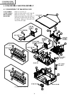
Страница 4: ...TERM PWB MAIN PWB MECHANISM CHASSIS CASSETTE HOUSING CONTROL F F 7 7 ANTENNA TERMINAL COVER EUR TERM PWB VC G200SM VC G20SM G201SM G401SM 2 DISASSEMBLY AND REASSEMBLY 2 1 DISASSEMBLY OF MAJOR BLOCKS TOP CABINET Remove 2 screws 1 FRONT PANEL Remove 2 screws 2 and 7 clips 3 MECHANISM Remove 2 screw 4 1 screw 5 MAIN PWB Remove 2 screws 6 and 2 screws7 with antenna terminal cover Remove 1screw 9 Remov...

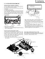
Страница 5: ...ng the terminal wire there is a possibility the capstan motor IC will damage The maximum applied voltage is 9V If more than 9V there is apossibility the mechanism will damage After ascertaining the return to the initial set position install the cassette housing in the specified position This method is applied only for the mechanism AH CONNECTOR AE CONNECTOR END SENSOR END TIP SW AA CONNECTOR AD CO...

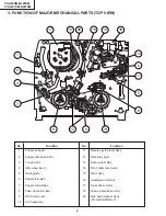
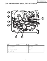
Страница 6: ...y 5 Open guide 6 Supply reel disk 7 Supply main brake 8 Take up main brake 9 Pinch drive cam 10 A C head ass y 11 Reverse guide lever ass y 12 Reel relay gear 13 Take up reel disk 14 Pinch roller lever ass y 15 Drum ass y 16 Loading motor block 17 Drum driver motor 18 Take up pole base ass y 26 Auto head cleaner Ass y VC G401SM ONLY 17 15 26 11 5 9 14 12 8 16 13 4 6 2 7 3 1 18 10 ...

Страница 7: ...C G201SM G401SM FUNCTION OF MAJOR MECHANICAL PARTS BOTTOM VIEW No Function No Function 19 Syncro Gear 20 Master cam 21 Capstan D D motor 22 Reel belt 23 Clutch lever 24 Limiter pulley ass y 25 Shifter 25 24 21 22 19 20 23 ...

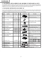
Страница 8: ...ration Remarks JiGTG0090 CM 3 Torque Gauge Head JiGTH0006 AW JiGRH0002 BR JiGSG2000 BS JiGSG0300 BF 7 JiGADP003 BK Tension Gauge These Jigs are used for checking and adjusting the reel disk height When fixing any part to the threaded hole using resin with screw use the jig Specified torque 5 kg This cassette torque meter is used for check ing and adjusting the torque of take up for measuring tape ...

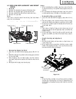
Страница 9: ...cked Abnormal rotation or significant vibration requires replacement Clean tape contact part with the specified cleaning liquid Clean tape contact area with the specified cleaning liquid Clean rubber and rubber contact area with the specified cleaning liquid Screen swaying Cassette not loaded or unloaded No tape running tape slack Tape slack Video head cleaning procedure 1 Apply one drop of cleani...

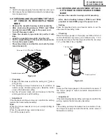
Страница 10: ...ORUNATAPEWITHOUTTHECASSETTE HOUSING CONTROL ASSEMBLY 1 Remove the full surface panel 2 Short circuit between TP803 and TP802 3 Plug in the power cord 4 Turn off the power switch The pole bases move into U L position 5 Open the lid of a cassette tape by hand 6 Hold the lid with two pieces of vinyl tape 7 Set the cassette tape in the mechanism chassis 8 Stabilize the cassette tape with a weight 500g...

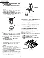
Страница 11: ...so that grease does not adhere the brake surface 2 After reassembly check the video search rewind back tension see 4 10 and check the brake torque see 4 14 Height checking and adjustment Note 1 Set the master plane with due care so that it does not contact the drum 2 When putting the master plane shift the reverse guide a little in the loading direction Care must be taken since excessive shift res...

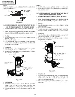
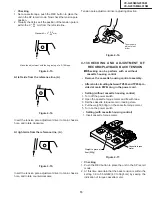
Страница 12: ...bly After short circuiting between TP803 and TP802 provided at main PWB plug in the power cord Setting 1 Set a torque gauge to zero on the scale Place it on the take up reel disk 2 Press the FF button 3 To calculate the remaining capacity of the play back mode slowly rotate the supply reel disk and then shift it into the forward mode Checking 1 Turn the torque gauge slowly one rotation every 2 to ...

Страница 13: ...t counterclockwise very slowly one rotation every 1 to 2 seconds and check that the torque is within the set value 14 1 3 5mN m 144 35gf cm Set value LP 6 9 mN m 70 gf cm Figure 4 8 Checking 1 Make sure that value is within the setting 6 9 mN m 70 gf cm 2 The winding up torque fluctuates due to variation of rotation torque of limiter pulley ass y Read the center value of fluctuation as setting 3 S...

Страница 14: ...ro vided at main PWB plug in the power cord Checking Press the play button to set the playback mode 1 Detach the pinch roller from the capstan shaft Do not separate excessively Or the pinch lever and pinch double action lever may disengage 2 Engage the tension gauge adapter with the pinch roller shaft and pull in the arrow direction 3 Gradually return the pinch roller and measure the pull ing forc...

Страница 15: ...g of a E 180 tape Figure 4 16 Figure 4 17 A A A Tensionpole adjustment driver C W C C W Cassette torque meter 500g Weight to prevent float 500g Standard A 0 mm 0 5 0 2 Checking 1 Push the REC button to place the unit in the SP record mode 2 At this time ascertain that the back tension is within the setting 3 9 to 5 5mN m 40 to 56gf cm by seeing the indication of torque cassette meter 0 5 0 2 Setti...

Страница 16: ...de brake torque is within the setting clean the felt surface of reel disk supply take up brake lever check again the brake torque If value cannot be set within the setting yet replace the main brake ass y or main brake spring Figure 4 18 4 14 CHECKING THE BRAKE TORQUE Checking the brake torque at the supply side Figure 4 19 Remove the cassette housing control assembly After short circuiting betwee...

Страница 17: ... 3 Unsolder the PWB fitted to the A C head Notes 1 When replacing never touch the head If you touched clean with the cleaning liquid 2 When removing the screw 3 take care so that the spring may out Figure 4 23 Note 1 If the screw 1 is tighten tentatively too loose the azimuth and height of A C head may change when they are finally tightened Therefore care must be taken 2 After completion of A C he...

Страница 18: ...refer to Figure 4 30 7 Turn the tilt screw to remove the tape crease at the fixing guide flange Playback the tape and check for tape crease at the fixing guide flange 1 If there is no tape crease Turn the tilt screw clockwise so that tape crease appears once at the flange and then return the tilt screw so that the crease disappears 2 If there is tape crease Turn counterclockwise the tilt screw so ...

Страница 19: ...audio output 5 The adjustment of 3 and 4 twice or three times repeat and finally adjust 4 Figure 4 27 For X value adjustment Adjust the X value turning the gear type screwdriver Figure 4 28 3 Tape run adjustment 1 Connect the oscilloscope to PB ATR signal output testpoint setoscilloscopesynctoEXT trigger input the PB CHROMA signal head switching pulse 2 Rough adjustment of X value TentativelyfixA ...

Страница 20: ...icture recorded tape and check the flatness of ATR signal waveform and sound Notes When the A C head X value adjustment is performed be sure to perform at first X value rough adjustment refer to 4 17 3 2 PB ATR Signal Head switching pulse Figure 4 29 4 A C head X value adjustment 1 Fix A C head arm screws 1 by the method described in 4 15 Replacement 3 2 Playback the alignment tape VROUBZFS and sh...

Страница 21: ...ass y 5 After installation adjust the playback switching point for adjustment of servo circuit 4 18 REPLACEMENT OF THE CAPSTAN D D DIRECT DRIVE MOTOR Remove the mechanism from the set Removal Follow the order of indicated numbers 1 Unsolder loading motor wire and drum FFC 2 Remove the reel belt 1 3 Remove the three screws 2 Reassembly 1 Taking care so that the capstan shaft does not contact the me...

Страница 22: ...otor replace ment 2 Remove the drum earth brush ass y 2 3 Remove the upper and lower drum assembly from main chassis 1 4 Remove the drum FFC holder 3 Cares when replacing the drum 1 Be careful so that the drum earth brush is not lost 2 Do not touch directly the drum surface 3 Fit gently the screwdriver to the screws 4 Since the drum assembly is an extremely precise as sembly it must be handled wit...

Страница 23: ...shown below 2 Fix the shifter position setting part to the roading arm T position setting part as shown in figure 3 Make sure tension arm not run on the shifter as shown in figure a b c Loading arm T Shifter Insert point Loading arm T Loading arm S Phase matting Not run on the sifter Sifter Tension arm a c b Drum Capstan D D motor Bottom side of mechanism chassis ...

Страница 24: ...eplacement loading motor as shown below Figure 4 40 Figure 4 38 2 The loading motor pressing in must be less than 196N 20 kgf Adjust the distance between motor and pulley to 6 95 mm Figure 4 38 1 Figure 4 39 0 2 0 15 E ring 6 95 mm A part Worm gear 0 0 15 Loading motor To press the motor in first receive it by portion A Apply grease Worm gear Apply grease Apply grease Apply grease L M Block Worm w...

Страница 25: ...er Proof lever spring and Holder R Figure 4 41 MSPRD0215AJFJ Proof lever spring fixing direction designated Take care that not to damage this parts out side out side inside bottom top MSPRD0212AJFJ Figure 4 42 Figure 4 43 2 0pen lever Sensor Plate and Frame R 3 Spring to Drive Arm R ...

Страница 26: ...SM VC G201SM G401SM 4 Frame R Frame L Drive Arm R Drive Arm L Upper Plate LANGF9661AJFW Top surface should be free from scratches or soil When assemble drive lever to frame R make sure the hole synchronize Figure 4 44 ...

Страница 27: ...eted Instruments required Blank video cassette tape DC voltmeter Screwdriver for adjustment Colour TV monitor Dual trace oscilloscope Alignment tape VROCBZF Servicing precations When the IC710 E2 PROM has been replaced make the following reprogramming Depending on models the IC710 E2 PROM has been factry adjusted for it s memory function It s therefore necessary to reprogram the memory function fo...

Страница 28: ...ort the TP801 at the main PWB By doing this LCD will all light up and become the PB Tracking Center value As for the recover equipment prepare the memory remote control But while adjust the running at non cassete control unit condition but have the cassete control JP TP801 short on the main PWB if press TRACKING UP and DOWN key at the same time it ll become the TRACKING CENTER for Running Ajustmen...

Страница 29: ...Vp p Y C CIRCUIT ADJUSTMENT ADJUSTMENT OF EE Level Confirmation VIDEO PAL Colour Bar 1Vp p Measuring instrument Mode Cassette Spectrum Analyzer Record Self recorded tape Test point YC CHIP Pin98 Specification 4 8MHz 100KHz ADJUSTMENT OF Deviation Confirmation VIDEO Colour Bar 1Vp p 3 80 4 80MHz A f Deviation Confirm the white peak frequency follow the standard value the deviation between shinkchip...

Страница 30: ...ure no black split at the mono sco picture during the self Rec PB when the S PICTURE is ON with the S PICTURE ON OFF make sure the picture level at the wedge part is change S PICTURE ON about 260 line S PICTURE OFF about 240 line Measuring instrument Mode Digital Voltmeter EE Specification 2 5 0 5V TUNER IF Circuit ADJUSTMENT ADJUSTMENT OF AFT Adjustment Confirmation except France Test point TU101...

Страница 31: ...ay eg JP 0 0 3 4 3 0 0 0 1 4 HEX CODE for Initial Jumper YC 34 34 07 07 PAL PAL NTSC NTSC SP LP EP SP EP VM F8FB Video Mode NOR__ ROM Version 1 During EE mode send the TEST Code R C code 47H to VCR and hold the Test code do not let go 2 While sending the TEST code the monitor screen will display the initial JP and Y C Rec Current setting Video mode and ROM Version condition 3 After confirmation Re...

Страница 32: ...ual load AT 39V AT between 39Vline GND DC 39 0V 2 0V actual load AT 25V AT between 25 5Vline GND DC 26 0V 1 0V actual load Measuring instrument Digital Voltmeter Setting Condition 1 Power Supply AC190V 50Hz 2 Surroung temperature Setting 20ºC 10ºC 3 Load connect place between AT 5V AC connector 8PIN AC connector1PIN High speed between AT25 5V AC5PIN AC2PIN Other model between AT12V AC5PIN AC2PIN W...

Страница 33: ... motor stops Start sensor close Cassette is judged caught halfway Cassette LED or some other part is judged defective 6 MECHANISM OPERATION FLOWCHART AND TROUBLESHOOTING GUIDE MECHANISM OPERATION FLOWCHART This flowchart describes the outline of the mechanism s operation but does not give its details 1 0 1 1 1 1 1 1 1 1 1 0 1 0 1 0 0 0 1 0 1 0 0 0 1 0 0 0 0 0 1 0 0 0 1 0 1 0 0 0 1 0 S Sensor Open ...

Страница 34: ...nd Stop capstan motor NO YES Press STILL key Pinch roller releasing Idler swinging Pinch roller pressing Loading motor turns reverse direction and master cam clockwise Turn capstan motor in reverse direction Turn loading motor forward direction Mode switch is at VSR position Set capstan motor to search speed Is take up reel sensor signal outputted Press REW key Release pinch roller Mode switch is ...

Страница 35: ... Mode SW at PB position Loading motor reverse direction Loading Motor stop rotate Loading motor stops End Loading motor turns in reverse direction and master cam clockwise 4 supply reel pulses outputted Does the take up reel pulse output two edges Capstan motor turns clockwise Loading motor turns reverse direction Mode switch is at Eject position Loading motor stops Capstan motor stops Press EJECT...

Страница 36: ...tem in trouble Does capstan motor turn in FF or REW direction Are idler wheel ass y and reel disk in mesh Is the pulse outputted from reel sensor The cassette tape is presumably damaged 2 REC PLAY FAILURE MODE RELEASE NO NO NO NO NO NO NO YES YES YES YES YES YES YES YES Is the master cam at PB position Does loading motor operate Modes changing smoothly through mode switch Loading motor control sys...

Страница 37: ...d supply reel disk in mesh Is supply reel disk winding torque normal Is pulse outputted from reel sensor Check main PWB YES YES YES YES YES NO NO NO NO NO YES YES NO NO YES Press REW key 4 i Unusual sound in cassette insertion and ejection mode Is unusal sound heard during cassette control running Unusual sound heard with pinch roller lever going up or down Is unusual sound heard during loading un...

Страница 38: ... gap found at reel disk Drive system out of contact with any part on main PWB Turn capstan motor by hand Unusual sound heard Check drive system s gears for damage Replace damaged gear with new one Reel disk Limiter pulley ass y Idler gear ass y Check reel disk and main chassis And replace defective parts Adjust reel disk height Rearrange the parts on main PWB ...

Страница 39: ...uit FLOW CHART NO 5 TIMER TROUBLESHOOTING 1 The LCD display fails to light up Is the supply voltage of 5V fed to pin 37 of IC8001 Check AT 5V line Is the supply voltage of 3 4V 1 7V feed to pin 38 and pin 39 of IC8001 Check pin 38 39 of IC8001 and peripheral circuits Is it possible to confirm signals LCD RESET LCD CS LCD CLOCK and LCD DATA on the pins 36 42 43 and 44 of IC8001 Are the segment sign...

Страница 40: ...sette tape in inserted Does pin 10 of P701 go to a H level when the cassette tape is inserted Does pin 87 of IC701 change from H to L level when the cassette tape is inserted Does the start sensor cover go to open when the cassette tape is inserted Does the key switch make good contact when the cassette tape is inserted Check switch contact Is there the function control voltage inputted at the pin...

Страница 41: ... pin 87 of IC701 Does the end sensor pulse at pin 86 of IC701 change from L to H level when the cassette tape is loaded Check line between end sensor and pin 86 of IC701 Does the master cam mode shifter operate normally when the cassette tape is loaded Check line between cam switch and IC701 Replace IC701 YES YES YES FLOW CHART NO 10 LOADING MOTOR AND EJECT TROUBLESHOOTING The cassette tape fails ...

Страница 42: ...01 1 6 2 7V Check line between the pin 91 of IC701 and pin 5 of P701 Is the supply voltage of 12V 25V fed to pin 2 of P701 YES Replace capstan motor Check MOTOR Vcc line and motor voltage selector circuit Q992 Q993 FLOW CHART NO 14 DRUM MOTOR TROUBLESHOOTING 2 The drum motor runs only for a few seconds Replace IC on mechanism Check peripheral circuit of IC on mechanism Is drum PG signal given out ...

Страница 43: ...ral circuit of pin 50 of IC701 C716 C715 and R708 Check drum FG signal line Is the head switching pulse at pin 23 of IC701 present NO See FLOW CHART NO 15 HEAD SWITCHING PULSE TROUBLESHOOTING YES YES Is the drum APC output at pin 34 of IC701 and drum AFC output at pin 32 of IC701 present NO Replace IC701 YES YES Is the drum control voltage applied to pin 12 of P701 YES Is pin 30 of IC701 in high i...

Страница 44: ...APC at pins 31 and 33 of IC701 Replace IC701 Replace A C head YES YES YES NO NO NO Is there capstan AFC signal at pin 31 of IC701 NO NO NO Is there capstan APC signal at pin 33 of IC701 YES NO Replace IC701 Does PB CTL signal appear at pin 76 of IC701 Replace IC701 Is there REC CTL signal output at pins 75 and 74 of IC701 Does PB CTL signal appear at pin 76 of IC701 Does A C head operate normally ...

Страница 45: ...to pins 63 and 62 of IC201 Check line between pins 63 62 of IC201 and pins 84 85 of IC701 Replace IC201 Is there a picture signal inputted in the pin 49 of IC701 YES NO NO Check peripheral circuit of Q251 YES Is there a picture signal outputted in the pin 47 of IC701 Is there a picture signal outputted in the pin 52 of IC201 Is there a picture signal outputted in the emitter of Q251 Check the line...

Страница 46: ... Is there luminance signal approx 0 5Vp p input and output at pins 13 and 14 of IC201 respectively NO NO Check parts around of X502 Athough picture record is possible colour does not appear E E mode is possible Is there luminance signal approx 0 3Vp p inputting at pin 42 of IC201 YES Is there luminance signal approx 0 5Vp p inputting at pin 26 of IC201 Check line between pins 18 and 19 of IC201 Ch...

Страница 47: ...tage of 5V applied to the chroma power terminal pin 61 of IC201 Is there chroma signal approx 156mVp p burst inputted at pin 46 of IC201 Is there chroma signal approx 197mVp p bust inputted at pin 58 of IC201 YES YES YES Is there luminance signal approx 0 5Vp p outputted at pins 52 of IC201 Check line between circuit of pins 24 and 23 of IC201 C210 See FLOW CHART NO 18 E E MODE TROUBLESHOOTING YES...

Страница 48: ...input terminal pin 7 of IC201 Is there audio signal outputted at pin 11 of IC201 Does the trap circuit operate normally NO NO NO Check line ranging from pin 39 of IC2501 DECODER or from SCART input terminal Check line ranging from SCART input terminal Check line ranging from Front A V input terminal J202 Line output terminal Is there audio signal inputted at pins 2 of IC2501 Check PC 5V lines Is t...

Страница 49: ... audio section power terminal at pins 14 of IC2501 Check signal line from video and audio function logic table as shown below Not output from 21pin connector in video and audio signal Linear Audio Double scart MODE SIG DECODER CIRCUIT SELECT INPUT SIGNAL FLOW SIG FLOW INPUT OUTPUT OUTPUT SIGNAL Pin47 of IC701 Y C video output E2 L2 video input Front video input pin7 pin28 pin25 E1 L1 video output ...

Страница 50: ...OFF are taken as 1 and 0 respectively The numbers JP0 to JP39 are divided into four groups and each group s setting is displayed in hexadecimal notation JP27 JP26 JP25 JP24 1 1 0 0 C JP23 JP22 JP21 JP20 0 0 0 0 0 JP19 JP18 JP17 JP16 0 0 0 0 0 JP15 JP14 JP13 JP12 0 1 0 0 4 JP11 JP10 JP9 JP8 0 0 1 1 3 JP7 JP6 JP5 JP4 0 0 0 0 0 JP3 JP2 JP1 JP0 0 0 0 0 0 Also recording level preset number selected fro...

Страница 51: ...screen upper left a Check the power on Power is ON b Make short circuit test point TP801 and hold the point Be sure that all the LCD display light up into the TEST mode YC 44220707 VM F8F9 NOR If the jumper setting is set as step 1 d it will be displayed on television screen like the example above 5 Finally release the test point to return to normal screen E E mode YC 4 4 2 2 0 7 0 7 V V V V SP LP...

Страница 52: ...DE 0 0 0 0 JP27 DNR 0 0 0 0 JP26 POST CODE 0 0 0 0 JP25 SAT CTL 0 0 0 0 JP24 AV LINK 16 9 0 0 0 0 JP23 Hi Fi 0 0 0 0 JP22 SORT CLOCK 0 0 0 0 JP21 DECODER 1 0 1 1 JP20 SURROUND 0 0 0 0 JP19 IGR 0 0 0 0 JP18 NICAM 0 0 0 0 JP17 G CODE1 0 0 0 0 JP16 G CODE0 0 0 0 0 JP15 EP 0 0 0 0 JP14 LP 0 0 0 1 JP13 F AV 0 0 0 0 JP12 2 SCART 1 0 1 1 JP11 RF OUTPUT OFF 0 0 0 0 JP10 TUNER2 0 0 0 0 JP9 TUNER1 0 0 0 0 J...

Страница 53: ...HANISMUS KASSETTEN GEHÄUSE F F 7 7 ANTENNEN ANSCHLUSS ABDECKUNG EUR TERM PLATINE VC G200SM VC G20SM G201SM G401SM 2 AUSBAU UND WIEDERZUSAMMENBAU 2 1 ZERLEGUNG DER WICHTIGSTEN BAUGRUPPEN OBERES GEHÄUSE 2 Schrauben entfernen 1 FRONTPLATTE Beide Schrauben 2 und 7 Klemmen 3 entfernen MECHANISMUS Zwei Schrauben 4 1 Schraube 5 HAUPTPLATINE 2 Schrauben 6 und 2 Schrauben 7 mit Antennenanschlussabdeckung e...

Страница 54: ...ASSETTENGEHÄUSES Beim Installieren des Kassettengehäuses auf dem Mechanismus ist die Anfangseinstellung von entscheidender Bedeutung Es gibt zwei Methoden für die Anfangseinstellung die elektrische und die mechanische Einstellung 1 Elektrische Anfangseinstellung Zur Anfangseinstellung des Mechanismus ist Schritt 1 der Installation des Kassettengehäuses durchzuführen Die Rückkehr zur Anfangspositio...

Страница 55: ...augruppe 4 Spannrollen baugruppe 5 Öffnen der Führung 6 Abwickel spulencheibe 7 Abwickel Hauptbremse Baugruppe 8 Aufwickel Hauptbremse Baugruppe 9 Andrucksteuerungsnocke 10 A C Kopfes 11 Baugruppe Rückwörtsführungshebel 12 Spulenrad 13 Aufwickel spulenscheibe 14 Baugruppe Andruckrollenhebel 15 Trommel 16 Laden des Motorblocks 17 Trommelgetriebemotor 18 Baugruppe Aufwickelstabbasis 19 Autom Kopfrei...

Страница 56: ...Nr Funktion Nr Funktion 19 Gleichlaufgetriebe 20 Hauptnocken 21 Capstan DD Motor 22 Spulenriemen 23 Kupplungshebel 24 Begrenzungsscheibe Baugruppe 12 Antriebsrad des Kassettensteuerteils 25 Umschalter FUNKTIONEN DER WICHTIGSTEN MECHANISCHEN TEILE UNTERANSICHT ...

Страница 57: ...wird Wird für die Einstellung ein Werkzeug benötigt ist sicherzustellen daß das richtige Werkzeug benutzt wird Nr Werkzeug Teile Nr Code Konfiguration Bemerkungen 1 Kassetten JiGVHT 063 CZ Drehmomentmesser Dieses Kassetten Drehmomentmesserät dient zur Prüfung und Einstellung des Aufwickeldrehmoments für die Messung der Bandvorspannung Drehmomentmesser 3 Drehmomentmesser Kopf JiGTH0006 AW Dieser We...

Страница 58: ...en Reinigungsflüssigkeit reinigen Die Walze des Reingers bei Verchleißauswechein Die AHC Walzeneinheit einfach gegen eine neue auswechsein Wartungsabstände Mögliche Störungen Obere und untere Trommel Baugruppe Seitengeräusche Kopf gelegentlich blockiert A C Kopf Ton leise oder verzerrt Schlechter Rauschspannungsabstand keine Farbe Schlechte Hüllkurvenflachheit mit Abgleichband Rücklaufführung Vorg...

Страница 59: ...e zwischen TP803 und TP802 kurz 3 Das Netzkabel anschließen 4 Den Netzschalter ausschalten Die Bolzensockel bewegen sich in die Position oben links 5 Den Deckel einer Kassette mit der Hand öffnen 6 Den Deckel mit zwei Vinylklebebandstücken geöffnet halten 7 Die Kassette in das Mechanismus Chassis einsetzen 8 Die Kassette mit einem Gewicht 500g stabilisieren damit sie sich nicht bewegt 9 Den Netzsc...

Страница 60: ...nradsabstimmenundeinenneuenAufwickelspulenteller auf die Welle setzen 3 Die Spulentellerhöhe prüfen und die Aufwickelhauptbremse Baugruppe montieren Hinweis 1 Aufpassen daß die Aufwickelhauptbremse Baugruppe nicht beschädigt wird und kein Fett an der Bremsfläche anhaftet 2 Nach dem Wiedereinbau die Rückspul Vorspannung beim Videosuchlauf prüfen Siehe 4 10 und das Bremsmoment prüfen Siehe 4 14 Höhe...

Страница 61: ...wickelspulenteller setzen 2 Die FF Taste drücken 3 ZumBerechnenderRestkapazitätimWiedergabemodus den Abwickelspulenteller langsam drehen und dann in den Vorlauf Modus umstellen Überprüfung 1 Den Drehmomentmesser langsam eine Umdrehung alle 2 bis 3 Sekunden von Hand im Uhrzeigersinn drehen 2 Sicherstellen daßderDrehmomentmesserkeinenWert niedriger als 30mN m 306gf cm anzeigt Einstellung 1 Wenn das ...

Страница 62: ...sser auf dem Abwickel spulencheibe setzen und sehr langsam eine Umdrehung alle 1 bis 2 Sekunden im Gegenuhrzeigersinn drehen überprüfen daß sich das Drehmoment innerhalb des Sollwerts von 14 1 3 5mN m 144 35gf cm befindet Überprüfung 1 Sicherstellen daß sich der Wert innerhalb des Sollbereichs von 6 9 mN m 70 gf cm befindet 2 DasAufspul DrehmomentschwanktinfolgevonAbweichungen des Rotationsmoments...

Страница 63: ...en Sie eine Kassette ein E 180 2 Nehmen Sie die Einstellung mit Anfang einer E 180 Kassette vor Drehmomentmesser Aufwickel spulenscheibe CCW Abbildung 4 10 Hinweis Den Drehmomentmesser fest auf den Aufwickelspulenteller setzen Sitzt er nicht fest auf dem Teller ist keine korrekte Messung möglich 4 11 PRÜFUNG DES ANDRUCKROLLEN DRUCKS Kassettensteuerteil entfernen NachKurzschließenderPrüfpunktezwisc...

Страница 64: ...euerteil entfernen NachKurzschließenderPrüfpunktezwischenTP803 und TP802 auf der Hauptplatine das Netzkabel anschließen Einstellung ohne Kassettensteuerteil 1 Den Netzschalter ausschalten 2 Das Kassetten Drehmomentmeßgerät öffnen und mit Klebeband geöffnet halten 3 Die Kassette in den Einfädelungszustand setzen 4 Das Gewicht 500g auf dan Kassetten Drehmoment messer legen 5 Den Netzschalter einscha...

Страница 65: ...r Kassettensteuerteil entfernen NachKurzschließenderPrüfpunktezwischenTP803 und TP802 auf der Hauptplatine das Netzkabel anschließen Einstellung 1 Vom Schnellvorlauf Modus in den STOP Modus umschalten 2 Das Netzkabel abtrennen 3 Einen Drehmomentmesser auf Null stellen und auf den Aufwickel spulenscheibe setzen 4 Sicher stellen dass die Spannrolle keinen Kontakt zum Spulenrad hat Aufspulseite Überp...

Страница 66: ...hnrads der A C Kopfplatte auf die eingestanzte Marke im Gehäuse ausrichten und die Schrauben 1 versuchsweise so fest ziehen dass sich die A C Kopfplatte reibungslos bewegt Das Anzugsmoment muss dabei bei 0 45 0 05N m 4 5 0 5kgf cm liegen Abbildung 4 23 Hinweis 1 Wenn die Schraube 1 versuchsweise zu locker festgezogen wird können sich beim endgültigen Festziehen Azimut und Höhe des A C Kopfes änder...

Страница 67: ... ist durch den Kopfschaltimpuls TP202 auszulösen 4 Das Abgleichband VROCPSV auf Wiedergabe stellen Abbildung 4 26 5 Die Spurlagentaste drücken und die ATR Signal wellenform von Maximum zu Minimum und von Minimum zu Maximum ändern Zu diesem Zeitpunkt sicherstellen daß sich die ATR Signal wellenform nahezu parallel verändert 6 Wenn sich die ATR Signal wellenform nicht nahezu parallel verändert die F...

Страница 68: ...sseite muß flacher sein Für X Wert Einstellung Den X Wert durch Drehen des Zahnrad Schraubendrehers einstellen 3 Einstellung des Bandlaufs 1 Das Oszilloskop an den Prüfpunkt für die Wiedergabe ATR Signal ausgabe die Oszilloskop Synchronisation auf EXT einstellen und das auslösende Wiedergabe CHROMO Signal Kopfschaltimpuls anlegen 2 Grobeinstellung des X Werts VersuchsweisedieSchrauben1desA C Kopfh...

Страница 69: ...mit der Methode wi in Abb 4 33 gezeigt bewegen und den A C Kopf so einstellen dass die maximale ATR Signal Wellenformerhaltenwird Hinweis Zumdiesem Zeitpunkt so einstellen dass die maximale ATR Sig nal Wellenform am nächsten zur A C Kopfpostion erhalten wird die bei Grobeinstellung des X Werts eingestellt wurde wie in 4 17 3 2 beschrieben 4 Den Wiedergabe Schaltpunkt einstellen Siehe Elektrische E...

Страница 70: ...pe schützen 5 Nach der Installation die Wiedergabe Schaltpunkt für die Einstellung der Servoschaltung einstellen 4 18 AUSWECHSELN DES CAPSTAN DD DIREKTANTRIEBS MOTORS Den Mechanismus von der Hauptleiterplatte entfernen Ausbau in der numerierten Reihenfolge 1 Lösen des Antriebsmotorkabels 2 Den Spulenriemen 1 entfernen 3 Die drei Schrauben 3 losdrehen Abbildung 4 32 Wiederzusammenbau 1 Die Position...

Страница 71: ...er Sorgfalt behandelt werden 5 Sicherstellen daßdieTrommeloberflächefreivonStaub Schmutz und Fremdstoffen ist 6 Nach dem Auswechseln der Trommel muß die Bandlaufeinstellung durchgeführt werden Anschließend auch die elektrische Einstellung durchführen Einstellung des Wiedergabe Schaltpunkts Einstellung und Prüfung der X Position Standard und x 3 Langsam Spurlageneinstellung 7 Die Trommel nach dem A...

Страница 72: ... am Einfädelrad auf der Abspulseite wie in Abbildung b beschrieben 3 Sicher stellen dass das Spannrad nicht auf dem Umschalter läuft wie in Abbildung c beschrieben Einfädelrad Abspulseite Umshalters Einklinkpunkt Einfädelrad Abspulseite Einfädelrad Aufspulseite Phasenanpassung Nicht auf dem Umschalter laufen lassen Umshalters Spannarm a c b Trommel Capstan DD Motor Unterseite des Mechanismus Chass...

Страница 73: ...ngsnocken Antriebsrad des Kassettensteuerteils Phasen anpassung Kerbe für den Andrucksteuerungsnocken Hauptnocken 4 23 INSTALLIEREN DES HAUPTNOCKENS AN DER RÜCKSEITE DES MECHANISMUS CHASSIS 1 Vor der Installation sicher stellen dass sich der Umschalter in der Anfangsposition befindet Rechte Seite der Bodenansicht 2 Den Hauptnocken wie unten gezeigt positionieren 3 Befestigen des E Rings Hinweis Si...

Страница 74: ...egebener Richtung Gehen Sie vorsichtig mit den Teilen um um sie nicht zu beschädigen außen außen innen unten oben MSPRD0212AJFJ Abbildung 4 42 Abbildung 4 43 2 Öffnungshebel Sensorplatte und Rahmen R 3 Feder zum Antriebsrad R 4 25 MONTAGE DES KASSETTENGEHÄUSES 1 Druckhebel Druckhebelfeder und Halterung R ...

Страница 75: ...SM G401SM 4 Rahmen R Rahmen L Antriebsrad R Antriebsrad L Obere Platte LANGF9661AJFW Die Oberfläche sollte frei von Kratzern und Schmutz sein Bei Einbau des Antriebshebels an den Rahmen R auf die Kerbe ausrichten Abbildung 4 44 ...

Страница 76: ...ich Benötigte Instrumente Farbbildschirm TV Unbespielte Videokassette Zweistrahlosziloskop Gleichstrom Voltmeter Abgleichband VROCBZF Schraubendreher für Einstellungen Vorsichtsmaßrahmen bei Wartungsarbeiten Wenn das IC710 E2 PROM ausgetauscht wurde die folgende Neuprogrammierung vornehmen In Abhängigkeit vom Modell ist das IC710 E2 PROM ab Werk auf die Speicherfunktion eingestellt Daher muß die S...

Страница 77: ...bgeschlossen Wenn sich die AUTO PG ADJ Funktion im manuellen Modus befindet den obigen Schritt 2 zuerst ausführen und dann die FF oder REW Taste drücken 1 Das bespielte Band wiedergeben 2 In den SLOW PB Modus bringen indem die SLOW Taste gedrückt wird 3 Den Prüfcode senden Fernsteuerungscode 47H oder TP801 auf der Hauptplatine kurzschließen 4 Den Störbalken auf de Unterseite des Monitor Bildschirm...

Страница 78: ...us Siehe nachfolgenden Hinweis Prüfpunkt VIDEO OUT 21polig oder RCA Anschluß 75 Ω Spezifikation 1 0 0 2 Vs s VIDEO PAL Farbbalken 1 Vs s EINSTELLUNG DES EE PEGELS Das Videoausgangssignal mit dem Oszilloskop überprüfen und mit der obigen Tabelle vergleichen V 200mV Teilung H 20µ sec Teilung Meßinstrument Betriebsart Kassette Spektrumanalysator Aufnahme Bespieltes Band Prüfpunkt YC CHIP 98polig Spez...

Страница 79: ...deaktivieren und sich vergewissern daß am Keil im Bildschirm eine Veränderung stattgefunden hat S PICTURE ON ca 260 Zeilen S PICTURE OFF ca 240 Zeilen EINSTELLUNG DES TUNER ZF SCHALTKREISES Meßinstrument Betriebsart Digitalvoltmeter EE Spezifikation 2 5 0 5 V Prüfpunkt TU101 Stift 23 E 12ch Eingangspegel 70 dBµ Während der Eingangskanal Testmodus gewählt wird die TEST R C Taste einmal drücken dann...

Страница 80: ...nd Y C Rec Current Confirmation EINSTELLUNG DES TIMER SCHALTKREISES Bildschirmanzeige Brückenliste Bildschirmanzeige Anzeigereferenz Bestätigung 1 Im EE Modus einen Prüfcode R C Code 47H zum VCR senden Prüfcode beibehalten nicht umschalten 2 Während der Prüfcode übertragen wird zeigt der Monitor Bildschirm die anfängliche JP und Y C Aufnahmestromeinstellung den Video Modus und die ROM Version an 4...

Страница 81: ...12V ATzwischen12 V LeitungundMasse Ausgang über 11 0 V 2 0 2 2 A Überlastung AT 25 0V ATzwischen25 5 V LeitungundMasse Ausgang über 25 0 V Wenn die Überlast alle 170 msec am Ausgang AT 12 V AT 25 0 V angelegt wird sicherstellen daß die Ausgangssignale jedes Mal 11 0 V 25 0 V betragen EINSTELLUNG DER LEISTUNGSAUFNAHME Meßinstrument Betriebsart Fixierte Last Leistungsaufnahme Gerät Strom ausgeschalt...

Страница 82: ...nlegen der Kassette Einfädeln JA JA JA NEIN NEIN NEIN Ausfädeln Einfädelmotor startet in normaler Richtung und Hauptnocken im Gegenuhrzeigersinn Springt der Mechanismus Positionsschalter innerhalb von 2 5 s heraus Sind Start Endsensor vor Einlegen der Kassette in niedriger Stufe Kassette einlegen Doppeltwirkender Einschub gleitet Trommelmotor startet Band wird eingefädelt Andruckrolle kommt in Kon...

Страница 83: ...r stoppt NEIN JA STILL Taste drücken Lösen der Andruckrolle Schwingen der Spannrolle Andrücken der Andruckrollen Einfädelmotor dreht sich entgegen dem Uhrzeigersinn und der Hauptnocken im Uhrzeigersinn Bandantriebsmotor in umgekehrte Richtung drehen Einfädelmotor entgegen dem Uhrzeigersinn drehen Nockenschalter befindet sich in VRS Position Bandantriebsmotor auf Suchlaufgeschwindigkeit einstellen ...

Страница 84: ...m Uhrzeigersinn Nockenschalter befindet sich in PB Position Einfädelmotor stoppt Ende Einfädelmotor dreht sich entgegen dem Uhrzeigersinn und der Hauptnocken im Uhrzeigersinn Werden 4 Abwickelspulen Impulse ausgegeben Gibt der Aufwickelspulen Impuls zwei Flanken aus Bandantriebsmotor dreht sich im Uhrzeigersinn Einfädelmotor dreht sich entgegen dem Uhrzeigersinn Nockenschalter befindet sich in Eje...

Страница 85: ...ebsmotor in FF oder REW Richtung Befinden sich Spannrollenrad Baugruppe und Spulenteller in Eingriff Wird der Impuls vom Spulensensor ausgegeben Das Cassettenband ist vermutlich beschädigt 2 VERSAGEN VON REC PLAY MODUSAUSLÖSUNG NEIN NEIN NEIN NEIN NEIN NEIN NEIN JA JA JA JA JA JA JA JA Befindet sich der Hauptnocken in der Wiedergabeposition Arbeitet der Einfädelmotor Werden die Betriebsarten einwa...

Страница 86: ... Spulmoment des Abwickelspu lentellers normal Wird der Impuls vom Spulensensor ausgegeben Hauptleiterplatte prüfen JA JA JA JA JA NEIN NEIN NEIN NEIN NEIN JA JA NEIN NEIN JA REW Taste drücken 4 i Ungewöhnliche Geräusche bei Einsetzen und Auswurf der Kassette Sind während des Kassettensteuerungslaufs ungewöhnliche Geräusche zu hören Sind ungewöhnliche Geräusche zu hören wenn sich der Andruckrollenh...

Страница 87: ...ebssystem nicht in Kontakt mit einem Teil auf Hauptleiterplatte Bandantriebsmotor von Hand drehen Ungewöhnliche Geräusche Die Zahnräder des Antriebssystems auf Beschädigung prüfen Beschädigte Zahnräder sind auszuwechseln Spulenteller Begrenzungsscheiben Baugruppe Spannrollenrad Baugruppe Spulenteller und Hauptchassis prüfen Defekte Teile auswechseln Spulentellerhöhe einstellen Die Teile auf der Ha...

Страница 88: ...R 5 STÖRUNGSSUCHE TIMER 1 Die LCD Anzeige leuchtet nicht auf Wird die Speisespannung von 5V an Stift 37 des IC801 geleitet STBY 5V Leitung überprüfen Wird die Spannung von 3 4 V 1 7 V den Stiften 38 und 39 von IC8001 zugeführt Die Stifte 38 und 39 des IC8001 und seine peripheren Schaltkreise überprüfen Können die Signale LCD RESET LCD CS LCD CLOCK und LCD DATA an den Stiften 36 42 43 und 44 des IC...

Страница 89: ...em Stift 2 des RMC801 zugeführt AT 5V und GND Leitung überprüfen Wird ein L Impuls von Stift 1 des Empfängers gesendet wenn die Infrarot Fernbedienung aktiviert wird Empfänger austauschen Die gesamte Schaltung zwischen Stift 1 des Empfängers und Stift 4 des IC701 überprüfen IC701 austauschen JA NEIN JA NEIN NEIN NEIN JA Ist das Kassettengehäuse verzogen Kassettengehäuse richten oderaustauschen NEI...

Страница 90: ...rüfen Wechselt der Impuls des Endsensors an Stift 86 des IC701beim Laden des kassette von L auf H Die Leitung zwischen dem Endsensor und Stift 86 von IC701 prüfen Funktioniert der Hauptnocken Modus wechsler beim Laden derKassette normal Die Leitung zwischen dem Nockenschalter und IC701 prüfen IC701 austauschen JA JA JA ABLAUFDIAGRAMM NR 10 STÖRUNGSSUCHE LADEMOTOR UND KASSETTENAUSWURF Die Kassette ...

Страница 91: ...von P701 und Stift 65 von IC701prüfen Wird der Kopfschaltimpuls von Stift 23 von IC701 ausgegeben IC701 überprüfen IC701 austauschen NEIN Trommelmotor überprüfen JA JA JA JA NEIN NEIN NEIN JA NEIN JA JA NEIN NEIN ABLAUFDIAGRAMM NR 15 STÖRUNGSSUCHE KOPFUMSCHALTIMPULS Kein Kopfumschaltimpuls Siehe ABLAUFDIAGRAMM NR 13 14 STÖRUNGSSUCHE TROMMELMOTOR 1 2 Dreht sich der Trommelmotor Liegen das Trommel I...

Страница 92: ...tung von Stift 50 von IC701 C716 C715 und R708 prüfen Die Trommel FG Signalleitung prüfen Liegt der Kopfumschaltimpuls an Stift 23 des IC701 an NEIN Siehe ABLAUFDIAGRAMM NR 15 STÖRUNGSSUCHE KOPFUMSCHALTIMPULS JA JA Liegt das Trommel APC Ausgang an Stift 34 des IC701 und der Trommel AFC Ausgang an Stift 32 des IC701 an NEIN IC701 austauschen JA JA Liegt die Trommelsteuerspannung an Stift 12 von P70...

Страница 93: ...IN Liegt ein Capstan AFC Signal an Stift 31 des IC701 an NEIN NEIN NEIN Liegt ein Capstan APC Signal an Stift 33 des IC701 an JA NEIN IC701 austauschen Liegt das PB CTL Signal an den Stift 76 des IC701 an IC701 austauschen Wird das REC CTL Signal an den Stiften 75 und 74 des IC701 ausgegeben Liegt an den Stift 76 des IC701 ein Wiedergabesteuer signal an Funktioniert der Ton Steuerkopf normal Höhe ...

Страница 94: ...tift 52 von IC201 ein Bildsignal ausgegeben Liegt die Versorgungsspan nung von 5 V Y Vcc an Stift 12 von IC201 an Liegen serielle Y C Daten und das Y C Taktsignal an den Stiften 63 und 62 von IC201 an Die Leitung zwischen Stiften 63 62 von IC201 und Stiften 84 85 von IC701 prüfen Den IC201 austauschen Die Leitung zwischen Stift 52 von IC201 und Stift 49 von IC701 prüfen Liegt die Versorgungsspan n...

Страница 95: ...rd die normale CCD Steuerspannung von ca 5 V dem Stift 37 über Stift 57 von IC201 zugeführt Wird das normale Taktsignal ca 8 86 MHz 0 5 Vs s für CCD dem Stift 44 über Stift 69 von IC201 zugeführt JA Obwohl eine Bildaufnahme möglich ist wird keine Farbe wiedergegeben Elektrisch Elektrisch Modus ist möglich Wird der Leistungsklemme des Chrominanz Bereichs an Stift 61 von IC201 eine Span nung von 5 V...

Страница 96: ... JA JA NEIN Liegt ein Chrominanzsignal ca 156 mVs s Burst an Stift 46 von IC201 an JA NEIN Wird dem Stift 58 von IC201 ein Chrominanzsignal zugeführt ca 197 mVs s Farbsynchronsignal JA JA Liegt ein Chrominanzsignal ca 300 mVs s Burst an Stift 54 von IC201 an Die Leitung zwischen den Stiften 55 und 54 von IC201 überprüfen IC201 ersetzen NEIN NEIN Den Peripherie Schaltkreis des Stifts 61 von IC201 u...

Страница 97: ...IC2501 DECODER oder vorderer Audiosignaleingang Stift 7 von IC201 Wird ein Audiosignal an Stift 11 von IC201 abgegeben Arbeitet der Auffangschaltkreis normal NEIN NEIN NEIN Die Leitung vom Stift 39 von IC2501 DECODER oder vom SCART Eingang prüfen Die Leitung vom SCART Eingang prüfen Die Leitung vom vorderen Audio Video Eingang J202 prüfen Leitungsausgang Wird ein Audiosignal an Stift 2 von IC2501 ...

Страница 98: ...SIGNAL A Stift 47 des IC701 Y C Videoausgang E2 L2 Videoeingang Vorderer Videoeingang Stift7 Stift28 Stift13 Stift25 E1 L1 Videoausgang 21POLIGER STECKER B C A B C Stift 58 des IC6301 Audioausgang L Kanal E2 L2 Audioeingang L Kanal Vorderer Audioeingang L Kanal Stift2 Stift33 Stift11 Stift42 E1 L1 Audioausgang L Kanal 21POLIGER STECKER A Stift 56 des IC6301 Audioausgang R Kanal E2 L2 Audioeingang ...

Страница 99: ...da im Prüfmodus sämtliche Anzeigelampen aufleuchten 3 Die CHANNEL und Tasten benutzen um die richtigen Funktionsnummern von JP0 bis JP39 anzuwählen Diese erscheinen im Display Bezug auf die E2PROM Tabelle Die DISPLAY Taste drücken um die Funktion ON zu aktivieren Die CLEAR Taste drücken um die Funktion aufzuheben OFF Die Tasten DISPLAY und CLEAR befinden sich auf der Fernbedienung Wenn die DISPLAY...

Страница 100: ...zeigen im Prüfmodus aufleuchten c Die Brückeneinstellung in hexadezimaler Notation und die Aufnahmestrom Einstellung wird im Monitor Bildschirm oben links dargestellt d Beispiel YC 44220707 VM F8F9 NOR Wenn die Brückeneinstellung gemä dem Schritt 1 d eingestellt ist wird diese wie im vorherigen Fall im Monitor Bildschirm angezeigt 5 Schlie lich den Prüfpunkt freigeben und zur normalen Bildschirman...

Страница 101: ...C CODE 0 0 0 0 JP27 DNR 0 0 0 0 JP26 POST CODE 0 0 0 0 JP25 SAT CTL 0 0 0 0 JP24 AV LINK 16 9 0 0 0 0 JP23 Hi Fi 0 0 0 0 JP22 SORT CLOCK 0 0 0 0 JP21 DECODER 1 0 1 1 JP20 SURROUND 0 0 0 0 JP19 IGR 0 0 0 0 JP18 NICAM 0 0 0 0 JP17 G CODE1 0 0 0 0 JP16 G CODE0 0 0 0 0 JP15 EP 0 0 0 0 JP14 LP 0 0 0 1 JP13 F AV 0 0 0 0 JP12 2 SCART 1 0 1 1 JP11 RF OUTPUT OFF 0 0 0 0 JP10 TUNER2 0 0 0 0 JP9 TUNER1 0 0 0...

Страница 102: ...102 VC G20SM G200SM VC G201SM G401SM 8 BLOCK DIAGRAM BLOCKSCHALTBILD SYSTEM SERVO BLOCK DIAGRAM SYSTEMS SERVO BLOCKSCHALTBILD ...

Страница 103: ...103 VC G20SM G200SM VC G201SM G401SM ...

Страница 104: ...104 VC G20SM G200SM VC G201SM G401SM SIGNAL FLOW BLOCK DIAGRAM SIGNALVERLAUF BLOCKSCHALTBILD ...

Страница 105: ... G201SM G401SM EE Signal PB Luminance Signal REC Luminance Signal EE Signal Wiedergabe Luminanzsignal Aufnahme Luminanzsignal PB Chrominance Signal REC Chrominance Signal Wiedergabe Chrominanzsignal Aufnahme Chrominanzsignal ...

Страница 106: ...106 VC G20SM G200SM VC G201SM G401SM AUDIO BLOCK DIAGRAM AUDIO SCHALTKREIS BLOCKSCHALTBILD VC G20SM G201SM G401SM ...

Страница 107: ...107 VC G20SM G200SM VC G201SM G401SM EE Signal PB Signal REC Signal E E Signal Wiedergabe signal Aufnahme sihnal ...

Страница 108: ...108 VC G20SM G200SM VC G201SM G401SM AUDIO BLOCK DIAGRAM AUDIO SCHALTKREIS BLOCKSCHALTBILD VC G200SM ...

Страница 109: ...109 VC G20SM G200SM VC G201SM G401SM EE Signal PB Signal REC Signal E E Signal Wiedergabe signal Aufnahme sihnal ...

Страница 110: ...110 VC G20SM G200SM VC G201SM G401SM POWER CIRCUIT BLOCK DIAGRAM HAUPTSTROMKREIS BLOCKSCHALTBILD ...

Страница 111: ...CKDOSE ZIEHEN 2 KÜHLKÖRPER VON HALBLEITERN SOLLTEN BEI BETRIEB DES CHASSIS ALS MÖGLICHE URSACHEN ELEKTRISCHER SCHALÄGE BETRACHTET WERDEN ANMERKUNG DiesesLeitungsschemaistdasoriginale Daherkann es von ihrem Leitungsschema etwas verschieden sein CAUTION This circuit diagram is original one Therefore there may be a slight difference from yours NOTES 1 The unit of resistance ohm is omitted k 1000 ohm ...

Страница 112: ...VC G201SM G401SM VOLTAGE MEASUREMENT MODE PB Parentheses REC Without Parentheses 9 SCHEMATIC DIAGRAM AND PWB FOIL PATTERN SCHALTSCHEMA UND PLATINENMUSTER MAIN CIRCUIT 1 HAUPTSCHALTUNG 1 1 SPANNUNGSMESSMETHODE WIEDERGABE Runde Klammern AUFNAHME Ohne runde Klammern ...

Страница 113: ...113 10 11 12 13 14 15 16 17 18 19 VC G20SM G200SM VC G201SM G401SM ...

Страница 114: ...A B C D E F G H I J VC G20SM G200SM VC G201SM G401SM VOLTAGE MEASUREMENT MODE PB Parentheses REC Without Parentheses SPANNUNGSMESSMETHODE WIEDERGABE Runde Klammern AUFNAHME Ohne runde Klammern MAIN CIRCUIT 1 HAUPTSCHALTUNG 1 2 ...

Страница 115: ...115 10 11 12 13 14 15 16 17 18 19 VC G20SM G200SM VC G201SM G401SM ...

Страница 116: ... A B C D E F G H I J VC G20SM G200SM VC G201SM G401SM VOLTAGE MEASUREMENT MODE PB Parentheses REC Without Parentheses MAIN CIRCUIT 2 HAUPTSCHALTUNG 2 SPANNUNGSMESSMETHODE WIEDERGABE Runde Klammern AUFNAHME Ohne runde Klammern ...

Страница 117: ...117 10 11 12 13 14 15 16 17 18 19 VC G20SM G200SM VC G201SM G401SM ...

Страница 118: ... A B C D E F G H I J VC G20SM G200SM VC G201SM G401SM VOLTAGE MEASUREMENT MODE PB Parentheses REC Without Parentheses MAIN CIRCUIT 3 HAUPTSCHALTUNG 3 SPANNUNGSMESSMETHODE WIEDERGABE Runde Klammern AUFNAHME Ohne runde Klammern ...

Страница 119: ...119 10 11 12 13 14 15 16 17 18 19 VC G20SM G200SM VC G201SM G401SM ...

Страница 120: ... A B C D E F G H I J VC G20SM G200SM VC G201SM G401SM VOLTAGE MEASUREMENT MODE PB Parentheses REC Without Parentheses MAIN CIRCUIT 4 HAUPTSCHALTUNG 4 SPANNUNGSMESSMETHODE WIEDERGABE Runde Klammern AUFNAHME Ohne runde Klammern ...

Страница 121: ...I J VC G20SM G200SM VC G201SM G401SM VOLTAGE MEASUREMENT MODE PB Parentheses REC Without Parentheses SPANNUNGSMESSMETHODE WIEDERGABE Runde Klammern AUFNAHME Ohne runde Klammern OPERATION CIRCUIT BEDIENUNGSSCHALTUNG BACK LIGHT CIRCUIT SCHALTUNG ...

Страница 122: ...G H I J VC G20SM G200SM VC G201SM G401SM VOLTAGE MEASUREMENT MODE PB Parentheses REC Without Parentheses EUR TERM CIRCUIT EUR TERM SCHALTUNG VC G20SM G201SM G401SM SPANNUNGSMESSMETHODE WIEDERGABE Runde Klammern AUFNAHME Ohne runde Klammern ...

Страница 123: ...123 10 11 12 13 14 15 16 17 18 19 VC G20SM G200SM VC G201SM G401SM ...

Страница 124: ...D E F G H I J VC G20SM G200SM VC G201SM G401SM VOLTAGE MEASUREMENT MODE PB Parentheses REC Without Parentheses EUR TERM CIRCUIT EUR TERM SCHALTUNG VC G200SM SPANNUNGSMESSMETHODE WIEDERGABE Runde Klammern AUFNAHME Ohne runde Klammern ...

Страница 125: ...125 10 11 12 13 14 15 16 17 18 19 VC G20SM G200SM VC G201SM G401SM ...

Страница 126: ...126 1 2 3 4 5 6 7 8 9 10 A B C D E F G H I J VC G20SM G200SM VC G201SM G401SM PWB FOIL PATTERN LEITERPLATTENFOLIENMUSTER MAIN PWB HAUPTLEITERPLATTE ...

Страница 127: ...127 10 11 12 13 14 15 16 17 18 19 VC G20SM G200SM VC G201SM G401SM ...

Страница 128: ...128 1 2 3 4 5 6 7 8 9 10 A B C D E F G H I J VC G20SM G200SM VC G201SM G401SM OPERATION PWB BEDIENUNGS LEITERPLATTE BACK LIGHT PWB LEITERPLATTE EUR TERM PWB EUR TERM LEITERPLATTE ...

Страница 129: ...05 D905 VHDERA2206 1Y V ERA2206 AC D906 VHDRL1N4005 1Y U RL1N4005 D908 VHD1SS119 1Y V 1SS119 AA D910 VHD1SS119 1Y V 1SS119 AA D911 RH EX0613GEZZY U Zener Diode D912 RH EX0645GEZZY V Zener Diode AB D914 RH EX0622GEZZY U Zener Diode D916 VHD1SS244 1Y V 1SS244 AB å D931 VHD10ELS4 1Y V 10ELS4 AD å D933 VHD15DF1FC 1E V 15DF1FC AD å D934 VHDSB240L 1E V SB240L AD D961 VHD1SS119 1Y V 1SS119 AA D963 RH EX0...

Страница 130: ...Ceramic AA C710 VCCCCY1HH180JS V 18p 50V Ceramic AA C713 VCKYCY1HF103ZS V 0 01 50V Ceramic AA C715 VCCCCY1HH101JS V 100p 50V Ceramic AA C716 VCKYCY0JB105KY V 1 6 3V Ceramic AC C717 VCKYCY0JF105ZS V 1 6 3V Ceramic AB C718 VCKYCY1HF103ZS V 0 01 50V Ceramic AA C721 VCKYCY1HF103ZS V 0 01 50V Ceramic AA Q702 RH PX0233GEZZ V PT493FL2 AD PACKAGED CIRCUITS X502 RCRSB0232GEZZ V Crystal AG X701 RCRSB0205GEZ...

Страница 131: ...VRD RA2BE681JY V 680 1 8W Carbon AA except G200SM R702 VRS CY1JF102JS V 1k 1 16W Metal Oxide AA R704 VRS CY1JF153JS V 15k 1 16W Metal Oxide AA C722 VCEA9M0JW107M V 100 6 3V Electrolytic AB C723 VCKYCY1HF473ZS V 0 047 50V Ceramic AA C724 VCKYCY1HF473ZS V 0 047 50V Ceramic AA C725 VCKYCY1HF103ZS V 0 01 50V Ceramic AA C726 VCKYCY1HB102KS V 1000p 50V Ceramic AA C728 VCKYCY1HF103ZS V 0 01 50V Ceramic A...

Страница 132: ...2k 1 16W Metal Oxide AA R827 VRD RA2BE333JY V 33k 1 8W Carbon AA R828 VRD RA2BE563JY V 56k 1 8W Carbon AA R835 VRD RA2BE562JY V 5 6k 1 8W Carbon AA R836 VRD RA2BE562JY V 5 6k 1 8W Carbon AA R837 VRD RA2BE562JY V 5 6k 1 8W Carbon AA R841 VRD RA2BE221JY V 220 1 8W Carbon AA R842 VRD RA2BE221JY V 220 1 8W Carbon AA R843 VRD RA2BE221JY V 220 1 8W Carbon AA R877 VRS CY1JF104JS V 100k 1 16W Metal Oxide ...

Страница 133: ...Oxide AA R2801 VRD RA2BE821JY V 820 1 8W Carbon AA R2809 VRS CY1JF000JY V 0 1 16W Metal Oxide AA R2821 VRD RA2BE680JY V 68 1 8W Carbon AA R2822 VRD RA2BE471JY V 470 1 8W Carbon AA R2823 VRD RA2BE101JY V 100 1 8W Carbon AA R2901 VRS CY1JF473JY V 47k 1 16W Metal Oxide AA R2904 VRD RA2EE821JY V 820 1 4W Carbon AA MISCELLANEOUS PARTS FB2501 RBLN 0077TAZZY V Ferrite Bead AB FB2801 RBLN 0077TAZZY V Ferr...

Страница 134: ...AA R2801 VRD RA2BE821JY V 820 1 8W Carbon AA R2803 VRS CY1JF000JY V 0 1 16W Metal Oxide AA R2809 VRS CY1JF000JY V 0 1 16W Metal Oxide AA R2810 VRS CY1JF000JY V 0 1 16W Metal Oxide AA R2821 VRD RA2BE750JY V 75 1 8W Carbon AA R2851 VRD RA2BE821JY V 820 1 8W Carbon AA R2861 VRD RA2BE750JY V 75 1 8W Carbon AA R2902 VRS CY1JF472JY V 4 7k 1 16W Metal Oxide AA R2903 VRD RA2BE821JY V 820 1 8W Carbon AA R2...

Страница 135: ...ARMP0062AJZZ V Loading Arm Supply AC 12 MLEVF0545GEZZ J Pinch Roller Lever Ass y AM 13 NBRGP0031AJZZ V Pinch Guide Bearing AB 16 LANGFA008WJFW V A C Head Plate AD 17 LHLDW1895AJZZ V A C Head FFC Holder AB 18 MLEVP0347AJZZ V Pinch Double Action Lever AC 19 MLEVP0344AJZZ V Reverse Guide Lever AE Ass y 20 MLEVP0342AJZZ V Loading Link Take up AB 21 MLEVP0343AJZZ V Loading Link Supply AB 23 MLEVP0346AJ...

Страница 136: ... Indicator G200SM G201SM G401SM 500 7 MSPRD0105AJFJ V Cassette Flap Spring AB 500 10 JBTN 3164AJSB V Button POWER AC except G20SM 500 11 GCOVA2214AJZZ V R C Cover G20SM AC 500 11 GCOVA2222AJZZ V R C Cover AC except G20SM 500 12 JBTN 3165AJSB V Button CH AC except G20SM 501 JBTN 3159AJSA V Button PLAY STOP AC G20SM 501 JBTN 3163AJSB V Button PLAY STOP AC except G20SM 502 JBTN 3162AJSA V Button REW ...

Страница 137: ...HANISCHE TEILE MECHANISM CHASSIS PARTS TEILE DES LAUFWERKCHASSIS A A 205 66 66 53 222 221 55 17 59 56 70 202 66 65 62 66 62 63 1 33 9 2 58 24 32 7 51 49 73 201 203 49 51 16 71 8 215 6 12 36 31 18 13 224 45 67 41 19 28 204 38 37 61 208 29 10 34 11 30 23 48 46 219 27 35 209 210 211 212 213 214 35 43 5 43 4 21 52 25 72 44 60 64 20 205 216 ...

Страница 138: ...138 7 6 5 4 3 2 1 A B C D E F G H VC G20SM G200SM VC G201SM G401SM CASSETTE HOUSING CONTROL PARTS CASSETTENGEHAUSE REGELTEILE A A 300 302 306 304 301 314 314 305 309 315 303 312 313 317 308 307 310 311 ...

Страница 139: ...G H VC G20SM G200SM VC G201SM G401SM MECHANICAL PARTS MECHANISCHE TEILE 605 615 605 603 616 604 E B C 601 610 603 611 600 606 C E A D D 612 606 608 A B 614 609 G G H H 617 620 619 607 602 617 620 613 VC G200SM VC G20SM G201SM G401SM ...

Страница 140: ...gly run on the cassette housing Keep the cassette cover about 45 open and make sure that the cassette cover open lever is between the front panel and the cassette cover Now fix the front panel in place Den Kassettenfachdeckel auf ca 45 offen halten und darauf achten daß sich der Öffnungshebel zwischen der Frontplatte und dem Kassettenfachdeckel befindet Frontplatte befestigen Die Frontplatte nicht...

Страница 141: ...he cassette housing Keep the cassette cover about 45 open and make sure that the cassette cover open lever is between the front panel and the cassette cover Now fix the front panel in place Den Kassettenfachdeckel auf ca 45 offen halten und darauf achten daß sich der Öffnungshebel zwischen der Frontplatte und dem Kassettenfachdeckel befindet Frontplatte befestigen Die Frontplatte nicht montieren w...

Страница 142: ...SET MARK Not Replacement Item Dry Battery QCNW 7870UMZZ 75 ohm Coaxial Cable SPAKCA064WJZZ Packing Case Accessories Operation Manual RRMCG0247AJSB Infrared Remote Control Unit SPAKP0051UMZZ Foam Bag SPAKXA019WJZZ Packing Pulp L SPAKXA018WJZZ Packing Pulp R ...

Страница 143: ...143 VC G20SM G200SM VC G201SM G401SM ...

Страница 144: ... in a retrieval system or transmitted in any form or by any means electronic mechanical photocopying recording or otherwise without prior written permission of the publisher SHARP CORPORATION AV Systems Group Quality Reliability Control Center Yaita Tochigi 329 2193 Japan DSMM P SUKM TQ1363 S Aug 2002 Printed in Japan In Japan gedruckt SA KY ...

Отзывы: