


40
VC-G20SM/G200SM
VC-G201SM/G401SM
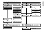
SWITC
FUNCTION
SWITC
FUNCTION
TERMINAL
Ref No. Ref No.
VOL
T
AGE
S805
SET
S801
POWER
0.000V
S806
CH(+)
S802
EJECT
0.652V
S807
P
AUSE
S803
MENU
1.864V
S808
REC
S804
CH(-)
2.561
V
S883
NO USE
S881
PLA
Y
S884/S885
REW
S882
ST
OP
3.081V
S886/S887
FF
TP801
TEST
3.694V
-
-
TP802
CASSETTE
4.279V
-
-
-
-
5.000V
KEY
-1 IN
KEY
-0 IN
(Pin88 of IC701)
(Pin89 of IC701)
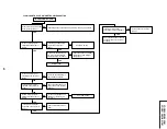
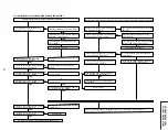
Is the cassette housing
distorted?
NO
YES
YES
YES
YES
NO
YES
NO
NO
YES
NO
YES
FLOW CHART NO.8 CASSETTE CONTROL
TROUBLESHOOTING(1)
A
cassette tape is not take in.
NO
NO
Check start sensor cover
.
Check line between start sensor
and pin(87) of IC701.
Check line between pin(92) of
IC701 and pin(10) of P701.
Is the supply voltage of 12V fed
to pin(8) of P701?
Check M 12V lines.
Check IC on mechanism.
Check line between IC on mechanism
and loading motor
.
Replace loading motor
.
Is the specified voltage applied
at the loading motor terminal
when the cassette tape is inserted?
Does IC on mechanism output
about 10V when the cassette
tape in inserted?
Does pin(10) of P701 go to a
"H" level when the cassette tape
is inserted?
Does pin(87) of IC701 change
from "H" to "L" level when the
cassette tape is inserted?
Does the start sensor cover go
to open when the cassette tape
is inserted?
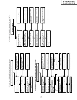
Does the key switch make good
contact, when the cassette tape is
inserted?
Check switch contact.
Is there the function control voltage
inputted at the pins(88) and (89) of
IC701, when the keys are activated?
Replace IC701.
Check peripheral circuit of pins(88) and
(89) of IC701, and the function keys.
YES
NO
NO
YES
Key-in input is not received
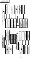
FLOW CHART NO.7 INFRARED R/C TROUBLESHOOTING
No operation is possible from the infrared remote control.
Does the infrared remote control
function?
Replace infrared remote control
as required.
Is the supply voltage of 5V fed to
pin(2) of RMC801.
Check
A
T
5V and GND lines.
Is "L" pulse sent out from pin(1) of
the receiver when the infrared remote
control is activated?
Replace receiver
.
Check between at pin(1) of receiver
and all the way up thru to pin(4) of
IC701.
Replace IC701.
YES
NO
YES
NO
NO
NO
YES
A/D KEY
INPUT
SPECIFICA
TION:-
FLOW CHART NO.6 TIMER TROUBLESHOOTING (2)
Fix or replace the cassette
housing.
Содержание VC-G200SM
Страница 103: ...103 VC G20SM G200SM VC G201SM G401SM ...
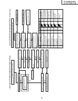
Страница 104: ...104 VC G20SM G200SM VC G201SM G401SM SIGNAL FLOW BLOCK DIAGRAM SIGNALVERLAUF BLOCKSCHALTBILD ...
Страница 106: ...106 VC G20SM G200SM VC G201SM G401SM AUDIO BLOCK DIAGRAM AUDIO SCHALTKREIS BLOCKSCHALTBILD VC G20SM G201SM G401SM ...
Страница 107: ...107 VC G20SM G200SM VC G201SM G401SM EE Signal PB Signal REC Signal E E Signal Wiedergabe signal Aufnahme sihnal ...
Страница 108: ...108 VC G20SM G200SM VC G201SM G401SM AUDIO BLOCK DIAGRAM AUDIO SCHALTKREIS BLOCKSCHALTBILD VC G200SM ...
Страница 109: ...109 VC G20SM G200SM VC G201SM G401SM EE Signal PB Signal REC Signal E E Signal Wiedergabe signal Aufnahme sihnal ...
Страница 110: ...110 VC G20SM G200SM VC G201SM G401SM POWER CIRCUIT BLOCK DIAGRAM HAUPTSTROMKREIS BLOCKSCHALTBILD ...
Страница 113: ...113 10 11 12 13 14 15 16 17 18 19 VC G20SM G200SM VC G201SM G401SM ...
Страница 115: ...115 10 11 12 13 14 15 16 17 18 19 VC G20SM G200SM VC G201SM G401SM ...
Страница 117: ...117 10 11 12 13 14 15 16 17 18 19 VC G20SM G200SM VC G201SM G401SM ...
Страница 119: ...119 10 11 12 13 14 15 16 17 18 19 VC G20SM G200SM VC G201SM G401SM ...
Страница 123: ...123 10 11 12 13 14 15 16 17 18 19 VC G20SM G200SM VC G201SM G401SM ...
Страница 125: ...125 10 11 12 13 14 15 16 17 18 19 VC G20SM G200SM VC G201SM G401SM ...
Страница 127: ...127 10 11 12 13 14 15 16 17 18 19 VC G20SM G200SM VC G201SM G401SM ...
Страница 143: ...143 VC G20SM G200SM VC G201SM G401SM ...


