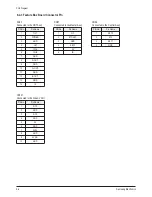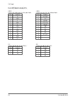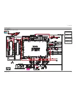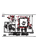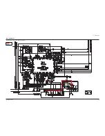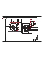
PCB Diagram
Samsung Electronics
9-7
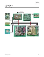
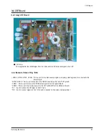
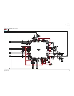
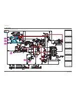
9-4 CRT Board
9-4-1 Assy CRT Board
2
0
C
N
C
1
0
C
N
C
1
V
F
1
N
F
1
0
5
T
G
2
0
5
T
G
5
0
5
T
G
6
0
5
T
G
3
0
5
T
G
4
0
5
T
G
■
CRT Drive
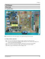
This supplies the final R/G/B signal from the F-Box and the CRT deflection signal to the CRT
9-4-2
Names & Roles of Key Parts
*
GT503, GT504, GT505, GT506 : This is a port for countermeasures against compulsory discharges and is connected to the
Power Board.
* GT503, GT504 : This is a port connected to the TBC-Wire and plays the role of CRT ground.
* CNC01 : This is a port to receive the R/G/B output signals from the System Board.
* CNC02 : This is a port that receives power for the CRT and AMP from the Deflection Board.
* FV1 : A port to connect the VM signal to the DY Ass'y.
* FN1 : A port to connect signals to the Tilt Coil and is required for the screen slant adjustment.
Содержание CS29Z30SPBXBWT
Страница 10: ...1 6 Samsung Electronics MEMO...
Страница 18: ...Alignment Adjustment 3 4 Samsung Electronics...
Страница 67: ...MEMO Samsung Electronics 5 24...
Страница 87: ...7 6 Samsung Electronics MEMO...
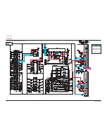
Страница 106: ...Samsung Electronics Schematic Diagram 10 9 10 4 CRT This Document can not be used without Samsung s authorization...
Страница 107: ...Schematic Diagram 10 10 Samsung Electronics 10 5 AV This Document can not be used without Samsung s authorization...
Страница 108: ...Samsung Electronics Schematic Diagram 10 11 10 6 CONTROL This Document can not be used without Samsung s authorization...
Страница 119: ...12 6 Samsung Electronics MEMO...

