


EB 8384-6S EN
169
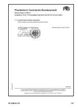
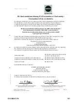
Revision Control Number: 0 / May 2012
Page 2 of 5
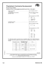
Addendum to EB 8384-6 EN
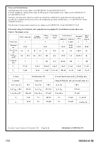
Notes
general for CSA Certification
:
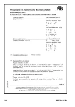
1.)
The apparatus may be installed in intrinsically safe circuits only when used in conjunction with
CSA / FM certified apparatus. For maximum values of U
i
or V
max
; I
i
or I
max
; P
i
or P
max
;
C
i
and L
i
of the various apparatus see Table 1, 2 and 3 on page 1 and 3
2.)
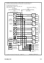
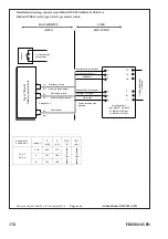
For barrier selection see Table 2 on page 3.
3.)
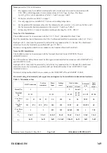
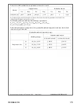
Use only supply wires suitable for 5°C above surrounding temperature.
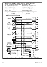
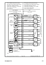
4.) For the permissible maximum values for the intrinsically safe circuits 1, 3, 4 and 6 see Table 1 and 2
For the permissible barrier parameters for the circuits 1, 2 and 6 see Table 2
5.) Cable entry M 20 x 1.5 or metal conduit according to drawing No. 1050 – 0540 T
Notes for CSA Installation:
The installation must be in accordance with the C. E. C. Part 1. (Canadian Electrical Code)
For CSA installation, Safety Barrier must be CSA Certified and installed in accordance with C.E.C. Part. 1
Each pair of I.S. wires must be protected by a shield that is grounded at the I.S. Ground. The shield must
extend as close to the terminals as possible install per C.E. Part 1.
Division 2 wiring method shall be in accordance to the Canadian Electrical Code Part 1.
Notes for FM Installation:
The installation must be in accordance with the National Electrical Code ANSI/NFPA 70 and
ANSI/RP 12.06.01
For FM installation, Safety Barrier must be FM approved and installed in accordance with ANSI/NFPA 70
and ANSI/RP 12.06.01
Each pair of I.S. wires must be protected by a shield that is grounded at the I.S. Ground
.
The shield must
extend as close to the terminals as possible install per National Electrical Code ANSI/NFPA 70 and
ANSI/RP 12.06.01
Division 2 wiring method shall be in accordance to the ANSI/NFPA 70 and ANSI/RP 12.06.01
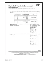
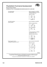
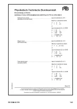
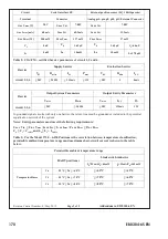
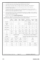
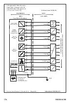
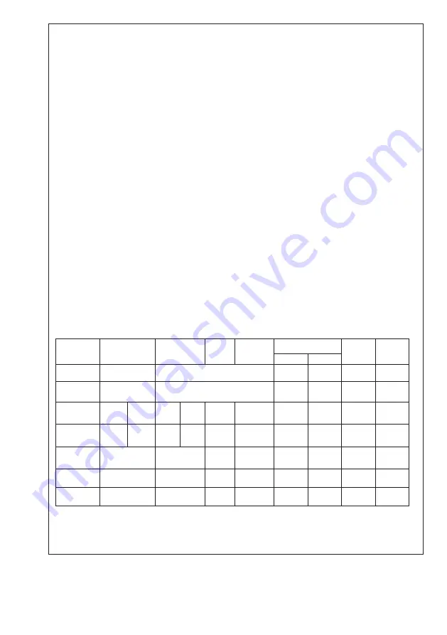
Electrical rating of intrinsically safe apparatus and apparatus for installation in hazardous locations.
Table 1: Maximum values
HART-connection
Position
transmitter
Binar-
Input
Leakage
sensor
Limit switches
Solenoid
valve
Fault
alarm
output
inductive software
Circuit No
.
1
2
3
4 and 5
6
7
Terminal
No.
11 / 12
31 / 32
41 / 42
41 / 42
51 / 52
81 / 82
83 / 84
U
i
or V
max
[V]
28 32 28 32 30 ###
16 20 28/32 20
I
i
or I
max
[mA]
115 87.5 115 87.5 100
###
25/52 60 115/87.5 60
P
i
or P
max
[W]
1
1
### ### 64/169 250 1 250
C
i
5.3nF
5.3nF 56.3nF 5.6nF 30nF 5.3nF 5.3nF 5.3nF
L
i
0µH
0µH
0µH C
0
1.4nF
100µH 0µH 0µH 0µH
Содержание TROVIS SAFE 3730-6
Страница 12: ...12 EB 8384 6S EN...
Страница 16: ...16 EB 8384 6S EN...
Страница 22: ...22 EB 8384 6S EN...
Страница 40: ...40 EB 8384 6S EN...
Страница 42: ...42 EB 8384 6S EN...
Страница 82: ...82 EB 8384 6S EN...
Страница 90: ...90 EB 8384 6S EN...
Страница 96: ...96 EB 8384 6S EN...
Страница 132: ...132 EB 8384 6S EN...
Страница 152: ...152 EB 8384 6S EN...
Страница 155: ...EB 8384 6S EN 155...
Страница 156: ...156 EB 8384 6S EN...
Страница 157: ...EB 8384 6S EN 157...
Страница 158: ...158 EB 8384 6S EN...
Страница 159: ...EB 8384 6S EN 159...
Страница 160: ...160 EB 8384 6S EN...
Страница 161: ...EB 8384 6S EN 161...
Страница 162: ...162 EB 8384 6S EN...
Страница 163: ...EB 8384 6S EN 163...
Страница 164: ...164 EB 8384 6S EN...
Страница 165: ...EB 8384 6S EN 165...
Страница 166: ...166 EB 8384 6S EN...
Страница 167: ...EB 8384 6S EN 167...
Страница 182: ...182 EB 8384 6S EN...
Страница 183: ...EB 8384 6S EN 183...


