12
EB 8048-2/-3 EN
Design and principle of operation
3
Design and principle of oper
-
ation
The Type 3349 Angle Valve is preferably
combined with a SAMSON Type 3271 or
Type 3277 Pneumatic Actuator (see Fig. 3)
as well as the Type 3379 Pneumatic Actuator
(see Fig. 4). The valve comes with welding
ends as standard. The valve is suitable for
aseptic applications and is designed without
any cavities.
The process medium flows through the valve
in the flow-to-close direction as indicated by
the arrow. The position of the valve plug de-
termines the flow rate across the cross-sec-
tional area of flow released between plug
and lathed seat.
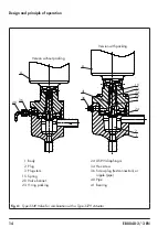
In the standard version, the plug stem is
sealed by the USP-VI diaphragm. In the spe-
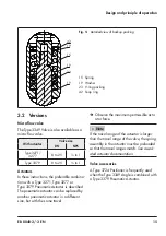
cial version, an additional backup packing is
used (see Fig. 5). The test connection allows
the diaphragm to be monitored for leakage.
In the version with backup packing, the test
connection is sealed by a stopper. The stop-
per must be replaced with a suitable leakage
indicator (e.g. a contact pressure gauge, an
outlet to an open vessel or an inspection
glass) when the valve is installed. The test
connection of valves without a backup pack-
ing is fitted with a pipe elbow to allow the
safe drainage of any medium that escapes.
When combined with the Type 3271 or
Type 3277 Actuator, the actuator stem and
plug stem are connected using stem connec-
tor clamps (A26/27). When combined with
the Type 3379 Actuator, the actuator stem
and plug stem are screwed together.
3.1
Fail-safe positions
The fail-safe position depends on the mount-
ed actuator. Depending on how the com-
pression springs are arranged in the pneu-
matic actuator, the valve has two different
fail-safe positions:
Actuator stem extends (FA)
When the signal pressure is reduced or the
air supply fails, the springs move the actua-
tor stem downward and close the valve. The
valve opens when the signal pressure is in-
creased enough to overcome the force exert-
ed by the springs.
Actuator stem retracts (FE)
When the signal pressure is reduced or the
air supply fails, the springs move the actua-
tor stem upwards and open the valve. The
valve closes when the signal pressure is in-
creased enough to overcome the force exert-
ed by the springs.
The direction of action of the Type 3271 and
Type 3277 Pneumatic Actuator can be re
-
versed, if required. Refer to the mounting
and operating instructions of the pneumatic
actuator:
u
EB 8310‑X for Type 3271 and Type 3277
Tip
Содержание EB 8048-3
Страница 25: ...EB 8048 2 3 EN 25...
Страница 54: ...54 EB 8048 2 3 EN...
Страница 55: ...EB 8048 2 3 EN 55...


