background image

32  

EB 8048-2/-3 EN

Operation

Operation

Immediately after completing mounting and 
start-up (see section 5), the valve is ready for 
use.

Type 3349‑1 and Type 3349‑7: crush haz

-

ard arising from moving parts (actuator and 
plug stem).
Do not insert hands or fingers into the yoke 
while the valve is in operation.

Risk of personal injury when the actuator 
vents.
Wear eye protection when working in close 
proximity to the control valve.

Risk of burn injuries due to hot or cold com

-

ponents and pipelines.
Depending on the process medium, valve 
components, and pipelines may get very hot 
or cold and cause burn injuries.
Wear protective clothing and safety gloves.

Risk of personal injury due to process 
medium escaping under pressure.


Align the pipe elbow to ensure that any es

-

caping process medium does not hit oper

-

ating personnel.


Wear protective clothing (eye protection, 
safety gloves) when working in close prox

-

imity to the control valve.

Risk of personal injury due to pressurized 
components and process medium escaping 
under pressure.
Do not loosen the screw of the test connec

-

tion while the valve is in operation.

Risk of impairment of aseptic or hygienic 
service.
In the version with backup packing, the test 
connection is sealed by a stopper. To guar

-

antee aseptic or hygienic service, connect a 
leakage detection device to the test connec

-

tion.

Operation disturbed by a blocked actuator 
or plug stem.
Do not impede the movement of the actuator 
or plug stem by inserting objects into their 
path.

Diaphragm damage through the use of an 
incompressible medium.
Closing the valve when the shut‑off valves 
upstream and downstream of the valve are 
closed may lead to the diaphragm rupturing 

WARNING

!

WARNING

!

WARNING

!

WARNING

!

WARNING

!

NOTICE

!

NOTICE

!

NOTICE

!

Содержание EB 8048-3

Страница 1: ...Type 3730 Electropneumatic Positioner Type 3349 3379 Control Valve with Type 3724 Positioner Edition March 2017 Type 3349 Aseptic Angle Valve with USP VI diaphragm In combination with an actuator e g...

Страница 2: ...er sales Service Department aftersalesservice samson de The mounting and operating instructions for the devices are included in the scope of delivery The latest documentation is available on our websi...

Страница 3: ...ures for preparation 20 4 1 Unpacking 20 4 2 Transporting and lifting 20 4 2 1 Transporting 21 4 2 2 Lifting 21 4 3 Storage 23 4 4 Preparation for installation 24 5 Mounting and start up 26 5 1 Mounti...

Страница 4: ...plug 40 7 3 Checking the concentricity of the plug to the plug stem 42 7 4 Preparation for return shipment 42 7 5 Ordering spare parts and operating supplies 43 8 Malfunctions 44 8 1 Troubleshooting 4...

Страница 5: ...ntended purpose or for damage caused by external forces or any other external factors Refer to the technical data and nameplate for limits and fields of application as well as possible uses Reasonably...

Страница 6: ...y or property damage plant operators and operating personnel must prevent hazards that could be caused in the control valve by the process medium the operat ing pressure the signal pressure or by movi...

Страница 7: ...onding system observe the requirements specified in section 6 4 of EN 60079 14 VDE 0165 Part 1 Referenced documentation The following documents apply in addition to these mounting and operating instru...

Страница 8: ...tuator does not vent at eye level Use suitable silencers and vent plugs Wear eye protection when working in close proximity to the control valve Risk of personal injury due to preloaded springs Valves...

Страница 9: ...tion e g solid particles in the pipeline The plant operator is responsible for cleaning the pipelines in the plant Flush the pipelines before start up Observe the maximum permissible pressure for valv...

Страница 10: ...y SAMSON u AB 0100 2 Markings on the control valve 2 1 Body inscription The details on the valve version are lasered onto the front and back of the valve body see Fig 1 No nameplate is used 2 2 Actuat...

Страница 11: ...psi 5 Max operating temperature C F 6 Flow coefficient KV CV Characteristic Equal percentage L Linear 7 Seat plug seal ME metal PK soft seal with PEEK PT soft seal with PTFE 8 Serial number 9 Configu...

Страница 12: ...ion of valves without a backup pack ing is fitted with a pipe elbow to allow the safe drainage of any medium that escapes When combined with the Type 3271 or Type 3277 Actuator the actuator stem and p...

Страница 13: ...nut 15 Spring 19 Washer 20 Flange 23 V ring packing 24 USP VI diaphragm 34 Hex screw 36 Screw plug test connection or nipple pipe 40 Pipe A7 Actuator stem A26 Stem connector clamps Valve with packing...

Страница 14: ...0 36 A 1 Body 2 Plug 3 Plug stem 15 Spring 20 Valve bonnet 23 V ring packing 24 USP VI diaphragm 34 Hex screw 36 Screw plug test connection or nipple pipe 40 Pipe 41 Bearing Version with packing Versi...

Страница 15: ...e replaced by another pneumatic actuator in a different size but with the same travel Observe the maximum permissible actu ator force If the travel range of the actuator is larger than the travel rang...

Страница 16: ...conformity Temperature range Depending on the version the control valve is designed for a temperature range from 0 to 160 C 32 to 320 F Leakage class Depending on the version the following leakage cl...

Страница 17: ...tors DN 15 20 25 32 40 50 65 80 100 NPS 1 1 1 2 2 3 4 H1 mm 238 241 244 276 279 285 293 348 360 L1 1 mm 70 105 150 G mm 86 113 144 Weight 2 kg 6 16 40 1 Length with welding ends DIN version Dimensions...

Страница 18: ...s of other connections u T 8048 3 2 Weight with welding ends Table 3 Dimensions of Type 3349 as micro flow valve for mounting onto Type 3379 Actua tor DN 8 10 15 20 25 NPS 1 Rated travel mm 7 5 L1 1 m...

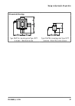
Страница 19: ...19 Design and principle of operation Dimensional drawings L1 H1 L1 G H1 G L1 L1 Type 3349 for mounting onto Type 3379 Actuator Standard version Type 3349 for mounting onto Type 3379 Actuator Micro flo...

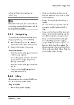
Страница 20: ...protective caps until im mediately before installing the valve into the pipeline 4 2 Transporting and lifting Hazard due to suspended loads falling Stay clear of suspended or moving loads Risk of lift...

Страница 21: ...ure and dirt Observe the permissible temperature range see section 3 3 4 2 2 Lifting Lifting equipment e g crane or forklift can be used to lift heavy control valves Lifting instructions Secure slings...

Страница 22: ...2 3 EN Measures for preparation Lifting points on the control valve Fig 6 Type 3349 1 without lifting eyelet Fig 7 Type 3349 1 with lifting eyelet Fig 8 Type 3349 7 without lifting eyelet Fig 9 Type...

Страница 23: ...2 2 5 After installation into the pipeline de pending on the type of connection e g welding joint flanged joint etc check whether the valve in the pipeline holds 6 Remove slings 4 3 Storage Risk of va...

Страница 24: ...lines in the plant Check the valve to make sure it is clean Risk of contamination of the process medium through the use of unsuitable lubricant and or contaminated tools and components Keep the valve...

Страница 25: ...EB 8048 2 3 EN 25...

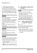
Страница 26: ...sk of contamination of the process medium through the use of unsuitable lubricant and or contaminated tools and components Keep the valve and the tools used free from solvents and grease Make sure tha...

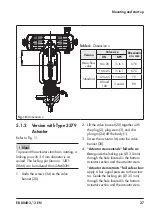
Страница 27: ...1 3 Screw the actuator A onto the valve bonnet 20 4 Actuator stem extends fail safe ac tion guide the locking pin 3 5 mm through the hole located in the bottom actuator section and the actuator stem A...

Страница 28: ...e pipeline 5 2 1 Checking the installation conditions Pipeline routing The inlet and outlet lengths vary depending on the process medium To ensure the control valve functions properly follow the insta...

Страница 29: ...ted or suspended The plant engineering company is responsible in this case Premature wear and leakage due to insuffi cient support or suspension In the following versions the control valve must be sup...

Страница 30: ...lve using suitable lifting equip ment to the site of installation see sec tion 4 2 Observe the flow direction through the valve The arrow on the valve indicates the direction of flow 4 Completely retr...

Страница 31: ...and smooth Open and close the valve observing the movement of the actuator stem Apply the maximum and minimum con trol signals to check the end positions of the valve Type 3349 1 and Type 3349 7 check...

Страница 32: ...g process medium does not hit oper ating personnel Wear protective clothing eye protection safety gloves when working in close prox imity to the control valve Risk of personal injury due to pressurize...

Страница 33: ...stream and downstream of the control valve 6 1 CIP cleaning in place CIP can be performed with commonly used cleaning fluids Observe the applicable hygiene regula tions 6 2 SIP sterilization in place...

Страница 34: ...e working on the valve residual process medium can escape and depending on its properties may lead to personal injury e g chemical burns Wear protective clothing safety gloves and eyewear Risk of burn...

Страница 35: ...the bends Re place the damaged diaphragm see sec tion 7 1 2 or 7 2 2 If the valve leaks even if the diaphragm is intact check the tightening torque of the joint between plug and plug stem as well as b...

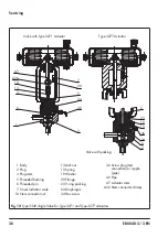
Страница 36: ...ing 19 Washer 20 Flange 23 V ring packing 24 Diaphragm 34 Hex screw 36 Screw plug test connection or nipple pipe 40 Pipe A7 Actuator stem A26 Stem connector clamps Valve with packing 20 5 34 40 6 1 13...

Страница 37: ...Apply a suitable lubricant to the thread of the plug stem 3 9 Screw a new plug 2 onto the plug stem 3 using a suitable tool Observe tight ening torques 10 Mark the side mounting position 11 Unscrew t...

Страница 38: ...dy 2 Plug 3 Plug stem 15 Spring 20 Valve bonnet 23 V ring packing 24 Diaphragm 34 Hex screw 36 Screw plug test connection or nip ple pipe 40 Pipe 41 Bearing A Actuator Fig 13 Type 3349 Angle Valve for...

Страница 39: ...22 Adjust lower or upper signal bench range See associated actuator docu mentation 7 2 Version with Type 3379 Actuator To prevent the actuator stem from rotating a locking pin with 3 5 mm diameter is...

Страница 40: ...ts over the plug stem into the packing chamber us ing a suitable tool 12 Compress the packing using a suitable tool and insert the snap ring 42 13 Screw the actuator A onto the valve bonnet 20 14 Actu...

Страница 41: ...le tool Observe tight ening torques 12 Mark the side mounting position 13 Unscrew the plug stem 3 from the plug 2 14 Insert a new diaphragm 24 into the new plug 15 Screw the new plug 2 back onto the p...

Страница 42: ...Type 3724 Positioner initialize the positioner u EB 8395 7 3 Checking the concentricity of the plug to the plug stem Before mounting the plug the concentricity of the plug to the plug stem must be ch...

Страница 43: ...r after sales service Declaration on Contamination 4 Send the valve together with the filled in form to your nearest SAMSON subsidi ary SAMSON subsidiaries are listed on our website at u www samson de...

Страница 44: ...he actuator Signal pressure too low Check the signal pressure Check the signal pressure line for leakage Actuator or plug stem does not move through the whole range Signal pressure too low Check the s...

Страница 45: ...amaged Replace the diaphragm see section 7 1 2 and 7 2 2 Contact SAMSON s After sales Service department for malfunctions not listed in the table Note 8 2 Emergency action Upon supply air or control s...

Страница 46: ...injuries Allow components and pipelines to cool down or heat up Wear protective clothing and safety gloves Diaphragm damage through the use of an incompressible medium Closing the valve when the shut...

Страница 47: ...line see section 4 2 9 3 Removing the actuator from the valve See associated actuator documentation 9 4 Disposal Observe local national and internation al refuse regulations Do not dispose of componen...

Страница 48: ...addresses of SAMSON AG its subsid iaries representatives and service facilities worldwide can be found on the SAMSON website in all SAMSON product catalogs or on the back of these Mounting and Operat...

Страница 49: ...1 Vaulx en Velin Cedex Beschreibung des Druckger tes Aseptisches Ventil Typ 3349 Geh usewerkstoff Schmiedestahl 1 4404 14435 A 182 F316L DN 15 25 DN 1 2 1 Die Ger te sind geeignet f r Medien gem ss Ro...

Страница 50: ...seal 6 Threaded pin 7 Travel indicator scale 10 Stem connector nut 13 Lock nut 15 Spring 16 Hanger 19 Washer 20 Flange assembly 23 V ring packing 24 USP VI diaphragm 34 Hex screw 36 Screw plug test co...

Страница 51: ...or Type 3379 Actuator 1 Valve body 2 Plug 3 Plug stem 6 Threaded pin 10 Stem connector nut 13 Lock nut 15 Spring 19 Washer 20 Valve bonnet 23 V ring packing 24 USP VI diaphragm 34 Hex screw 36 Screw p...

Страница 52: ...ded bushing or stem seal 6 Threaded pin 7 Travel indicator scale 15 Spring 16 Plate 19 Washer 20 Flange assembly 23 V ring packing 24 USP VI diaphragm 34 Hex screw 36 Screw plug test connection or nip...

Страница 53: ...icro flow valve version for Type 3379 Actuator 1 Valve body 2 Plug 3 Plug stem 6 Threaded pin 15 Spring 19 Washer 20 Valve bonnet 23 V ring packing 24 USP VI diaphragm 34 Hex screw 36 Screw plug test...

Страница 54: ...54 EB 8048 2 3 EN...

Страница 55: ...EB 8048 2 3 EN 55...

Страница 56: ...2018 11 02 English SAMSON AKTIENGESELLSCHAFT Weism llerstra e 3 60314 Frankfurt am Main Germany Phone 49 69 4009 0 Fax 49 69 4009 1507 samson samson de www samson de EB 8048 2 3 EN...

Отзывы: