background image

21

Instruction Manual

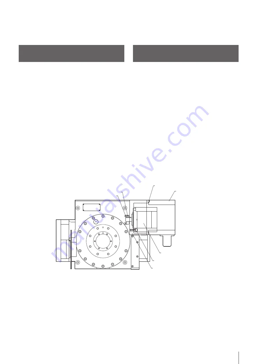
7-2  모터교환 시 커버 탈착방법

7-2   Removal ad installation of cover 

replacing the motor

[ 그림 / Fig.8 ]

1)  ① MOTOR COVER를 고정하는 ② WRENCH BOLT 4개를 제거 합니다. 

(주의 : ① MOTOR COVER를 탈거하면 닿는 면에 O-RING이 있습니다. 
O-RING이 분실 및 파손 되지 않도록 주의 합니다.)

2)  이 때, 연결된 내부의 케이블을 분리한 후, 손상 되지 않도록 주의 하면서 

① MOTOR COVER를 탈거 합니다.

3)  ④ BODY에 고정된 ⑤ SERVO MOTOR를 고정하고 있는 ③ WRENCH 

BOLT 4개를 제거 합니다.

4)  모터를 탈거 한 후, ⑦ GEAR와 함께 체결 되어 있는 ⑥ WRENCH BOLT 

6개를 제거 합니다. (주의 : ⑤ SERVO MOTOR 를 제거 하면 이물질이 유
입 되지 않도록 O-RING이 있습니다. O-RING이 분실 및 파손 되지 않도
록 주의 합니다. )

5)  ⑦ GEAR와 함께 분해되는 KEY, RING 등을 분해 한 후에 모터를 교체 합

니다.

6)  모터를 교체 하면 ⑦ GEAR와 함께 KEY와 RING을 조립하고 ⑦ GEAR를 

지지 하는 ⑥ WRENCH BOLT 6개를 체결 합니다.

7)  이전에 사용 했던 O-RING를 BODY에 조립 후, ⑤ SERVO MOTOR를 기

준경에 맞추어서 끼워 넣습니다.

8) ③ WRENCH BOLT 4개를 ⑤ SERVO MOTOR 체결부에 고정 합니다.
9) ① MOTOR COVER 내부에 연결되어 있는 케이블을 정리 합니다.
10)  ④ BODY 면에 O-RING을 끼워 넣은 후, ① MOTOR COVER와 ② 

WRENCH BOLT 4개를 이용하여 조립 합니다.

1)  To remove the ②wrench bolt 4 one to fix the ①motor cover (note: 

careful .O-ring is not lost or damaged ①motor cover to the plane hit 
and to decompose there is o-ring)

2)  In this case, after you remove the internal connection cable, being 

careful not to damage, and disassemble the ①motor cover.

3)  Disassemble the ⑤servo motor fixed ③wrench bolt 4ea that is fixed 

to the ④body.

4)  After disassembling the motor, remove the ⑥wrench bolt 6ea that are 

fastened together with the ⑦gear. (Note: when you delete a ⑤servo 
motor, please be careful .O-ring is not lost or damaged there is o-ring 
so that foreign matter does not enter.)

5)  After disassembling. Key and ring is decomposed with ⑦gear, replace 

the motor.

6)  Assemble the key and ring with ⑦gear to replace the motor and then 

entered into a ⑥wrench bolt 6 ea to support the ⑦gear.

7)  After assembling the o-ring, which has been used in body before, and 

insert to fit the ⑤servo motor to the reference diameter.

8)  ③Wrench bolt 4ea that you fixed to ⑤servo motor fastened
9) Clean the cables that are connected to the internal ①motor cover
10)  Insert o-ring on ④body surface, assemble ①motor cover by using 

②wrenchbolt 4ea.

모터에 절삭유가 침투하지 않도록 모터커버와 몸체 사이의 연결부분에
O-RING 이 설치되어 있습니다.
모터커버 및 케이블 파손 때문에 절삭유가 모터커버로 들어가면
전기장치(모터, 솔레노이드 밸브 등)가 손상되므로 주의를 요하며 만약
손상되면 새 부품으로 즉시 교체해야 합니다.

An O-ring is provided between the motor cover and main body to
prevent the cutting fluid from entering the motor.
If the cutting fluid enters the motor cover due to damaged motor cover
or cable, the electric devices (motor, solenoid valve, etc.) can be
damaged. Damaged parts/components must be replaced with new
parts/components immediately.

7.2.1. 방수대책

7.2.1. Waterproofing Measures

① MOTOR COVER

④ COUPLING

⑤ SETSCREW

② WRENCH BOLT

③ WRENCH BOLT

⑦ SERVO MOTOR

⑥ MOTOR PLATE

Содержание SR-200

Страница 1: ...Maunted Series Instruction Manual SR 200 SR 250 1 Please read the DANGER and Warning sections before operating the NC Rotary Table Please keep this manual handy as it may answers to any questions you...

Страница 2: ...2 NC Rotary Table...

Страница 3: ...tion Warning term DANGER WARNING CAUTION IMPORTANT DANGER WARNING CAUTION IMPORTANT Indicates an imminently hazardous situation which if not avoided will result in death or serious injury These warnin...

Страница 4: ...14 4 3 1 Air Clamp System 1 4 4 4 Air Purge System 15 4 5 15 5 16 5 1 16 5 2 16 6 16 6 1 NC Rotary Table Clamp 16 6 2 Clamp Unclamp 17 6 3 Clamp Unclamp Solenoid Valve 17 7 18 7 1 18 7 1 1 Worm Gear B...

Страница 5: ...ion 1 6 5 2 Periodic Inspection 1 6 6 Description of the NC Rotary Table 16 6 1 Cautions for the Table Clamp 1 6 6 2 Clamp Unclamp Check Device 1 7 6 3 Solenoid Valve for Clamp Unclamp 1 7 7 Descripti...

Страница 6: ...machinery and the controllers for installation prior to start installation maintenance or repair of the tilting NC rotary table Loose clothing or limbs may get caught during operation Tighten the bol...

Страница 7: ...y workpieces Damage may occur Excessively long or heavy workpieces may result in them being thrown from the rotary table NC Do not exceed the allowable cutting force Product may be damaged and or work...

Страница 8: ...Use eyebolts and wireropes when moving the NC rotary table Dropping the rotary table will cause damage and possibly injury CAUTION CAUTION 6 NC Change the lubricant every six months Actual change cycl...

Страница 9: ...ompressed air through the air combination lubricator mist separator regulator drain the com pressed air inlet is located on the motor case Drain air filter regularly an auto drain system is recommende...

Страница 10: ...earance drawing The maximum table rotation speed is the value at Motor 3000min In order to meet the specifications of the motors attached with absolute encoders the starting point origin of the machin...

Страница 11: ...value Model 1 Run out of Table face in rotation 0 020 SR 200 SR 250 2 Parallelism between center of hole and Base 0 020 3 Squareness between Table face and base 0 020 at Table Dia 4 Center hole run ou...

Страница 12: ...he gap between the T slot and the guide block is large install the product close to either side of the T slot 4 Use a clamping device to securely fasten the NC rotary table to the machine tool 4 1 1 4...

Страница 13: ...he old oil and do not allow any debris of foreign material to enter the tank If contaminated with foreign material the bearings may become stuck and accuracy may diminish Use the following lubricant R...

Страница 14: ...oil dust removed page 9 2 Connect the air hose to the air inlet The air inlet PT 1 4 is located on the motor casing See the outside drawing for installation 3 The supply pressure of the air should be...

Страница 15: ...thus air pressure is applied to the motor cover As such the air exit must be kept open When the air is discharged out the operator can hear the sound The hydraulic clamping system requires an addition...

Страница 16: ...amaged cable 3 Corrosion open circuit in the motor casing CAUTION CAUTION CAUTION The Rotary Table must be rotated while unclamped and processing after positioning must be performed while clamped Inco...

Страница 17: ...g are as follows which must be taken into consideration into the electric wiring Solenoid ON table unclamp Solenoid OFF table clamp 6 2 6 2 Clamp Unclamp Check Device 4 To prevent mistakes be sure to...

Страница 18: ...eration is less than the optimal value due to thermal expansion Worm gear will not move if backlash is excessively low Measure backlash before adjusting CAUTION CAUTION Appropriate Backlash 1 T SOLT 2...

Страница 19: ...using hands Insert a T wrench into the hexagonal recess of the worm shaft Note refer to Worm Gear Backlash Adjustment page 18 of this manual The backlash is reduced when the housing is turned clockwis...

Страница 20: ...eripheral devices of the table to confirm that the adjustment is satisfactory HOUSING PLUG O RING O RING OIL CAUTION When installing the housing plug take care not to damage the O ring Fig 6 IMPORTANT...

Страница 21: ...o motor please be careful O ring is not lost or damaged there is o ring so that foreign matter does not enter 5 After disassembling Key and ring is decomposed with gear replace the motor 6 Assemble th...

Страница 22: ...and cutting fluid from the Table completely and put it on rigid wooden plate to maintain accuracy Apply rust preventive oil to the Table and case or protect them with a wooden cover or wrap them with...

Страница 23: ...mulated pitch error of 0 05 with Equation 2 yields Therefore the angle is 206 seconds or three minutes and 26 seconds As illustrated above the lengths and the angles of the peripheral devices are conv...

Страница 24: ...8 C1 706 Samchully Machinery 405 820 99 TEL 032 822 4811 FAX 032 822 4377 405 820 99 Namdong daero Namdong gu Incheon TEL 82 32 899 8965 FAX 82 32 721 7607 1544 3122 NC NC Rotary Table Rear Maunted Se...

Отзывы: