Operating manual
Rear disc mowers with central suspension
- with hydro-pneumatic or spring suspension
- 3 9 -
ATTENTION:
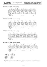
Since the mowing width is different in the mowers manufactured by us (and
different directions of disc rotation) the disc rotation direction should be
verified before blade installation (Fig. 22).
WARNING:
Due to the high revolutions of the discs, blade holders should be replaced in
pairs of the same weight - every holder has its weight stamped on it.
Otherwise, the resulting lack of balance will cause the disc to vibrate and may
cause damage to the cutterbar guard.
ATTENTION:
Installing the blade the wrong way will cause big furrows of grass. When
installing blades, pay special attention to the rotation direction of the blade on
the holder.
6.4.
Setting mowing height
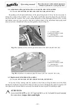
The desired mowing height is obtained through changing
the length of the upper regulated tie S (Fig. 9) of the suspension.
Extending the tie increases and shortening it decreases mowing height.
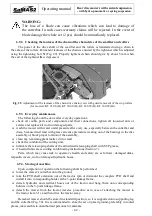
Mowing height is shown by the indicator located on the suspension
frame (Fig. 23), recommended height is 6 - 7 cm.
Fig. 23. Mowing height indicator
6.5.
Use and adjustment of the load reducing chain
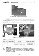
Fig. 24a. The load reducing chain
Fig. 24b. Height of the mower in the operating
position
The load reducing chain is used to set a permanent height of the mower during operation. It
facilitates the correct positioning of the mower for operation and reduces the load on the hydraulic
actuator of the tractor.
When connecting the mower to the tractor we insert fitting A (Fig. 24a) of the chain onto
the pin B of the upper tie. The length of the chain should be adjusted so that in operating position
the mower is at a height shown on (Fig. 24b) and the tilt of the mower.
A
B
a)
~40 cm
b)

