


Operating manual
Rear disc mowers with central suspension
- with hydro-pneumatic or spring suspension
- 3 3 -
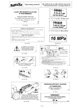
ATTENTION:
If the purchaser of the mower does not own the safety equipment mentioned
above it can be purchased from the mower's manufacturer.
WARNING:
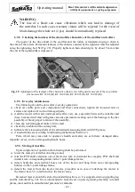
Do not drive on public roads if the machine's transport height is more than
4 m (for mower KT 340 – when transported, transport height should be
lowered on the tractor links – Fig. 15).
ATTENTION:
If it is necessary reduce the length of the shaft according to its user's manual.
WARNING:
The articulated telescopic shaft should remain connected only during mower
operation. During transport or any servicing operations the shaft should be
disconnected from the PTO of the tractor.
ATTENTION:
Use machines with PTO shafts designed to drive them. Prior to the work
commencement, safety guards should be checked whether they (in the tractor,
the mower and the PTO shaft) are placed correctly and not damaged.
Damaged or missing parts must be replaced with genuine ones. Make sure
whether the PTO shaft is properly mounted. Approaching the rotating parts is
strictly forbidden, as it may lead to serious injuries or even death. For any
service and repair works of the shaft and the mower, the tractor engine and its
drive must be disconnected while ignition key off. Prior to the operation
commencement, read the operator's manuals of both the machine and the PTO
shaft.
ATTENTION:
The articulated telescopic shafts should always be connected with
the unidirectional right clutch end to the mower.
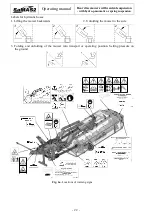
5.8.
Changing the mower position from transport to operating position
open the shut-off valve on the actuator (Fig. 14),
lower the mower on the TPH of the tractor so that the pins of the suspension frame are at
a minimum of 400 mm above the ground (Fig. 15),
make sure that the space where the mower will be opened is unobstructed and free of people,
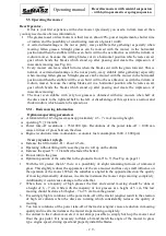
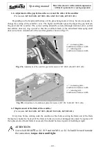
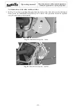
pull the line enough to release the locking lever Z (Fig. 13) and engaging the external hydraulic
valve on the tractor and the hydraulic hoist of the tractor, position the cutting unit into
a horizontal position,
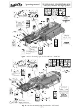
using the lever of the external hydraulic system of the tractor lower the cutting unit so that as it
gets closer to the ground it slows down,
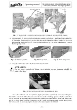
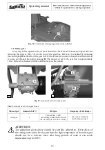
release the line of the lock, lower the mower until the load reducing chain is taut. If the pins of
the mower's suspension are lower than 40 cm from the ground (Fig. 21b), chain length should
be reduced,
unlock the coping tie,


