


Operating manual
Rear disc mowers with central suspension
- with hydro-pneumatic or spring suspension
- 3 0 -
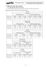
6.
With re-cultivated pastures during first mowing or after long lasting heavy rains it is necessary
to reduce the pressure of the bar on the ground by adjusting the spring or the hydro-pneumatic
suspension.
ATTENTION:
The mower could leave a small furrow in the middle of the cut because of
the push of the air resulting from the cutting disc rotating in opposite
directions.
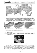
WARNING:
Tilting the mower back is forbidden as it wil cause faster wear or even
damage of the cutterbar.
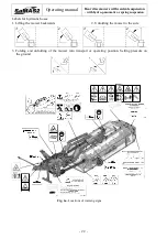
5.5.2.
Mower positioning during directional changes
Raise the mower using the hydraulic lift (Position 2 Fig. 3) and turn around. The height of
the raised mower is enough to drive over mowed grass without additionally raising the mower on
the TPH of the tractor.
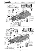
5.5.3.
Mower clogging
When operating the mower pay attention to variable conditions on field, which may influence
the mower clogging, such as: terrain unevenness, height and density of grass as well as other
objects in the grass. In order to avoid clogging, mowing speed should be adjusted to the mentioned
conditions. In order to remove the machine clogging, cutterbar should be lowered onto the ground
while the drive must be disconnected with ignition key off.
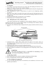
5.6.
Preparing the mower for transport
The following is required to prepare the mower connected to a tractor for transport -
movement on public roads:
lift the mower with tractor hydraulic lift onto the tractor links until the lower lift pins of
the mower 3-point linkage frame are raised above the ground:
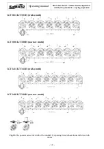
a)
about 15 cm in case of KT 341 (H) and KT 340 (H),
b)
about 40 cm in case of other models of KT (Fig. 15),
lower the transport height on the tractor links, so it does not exceed 4 m,
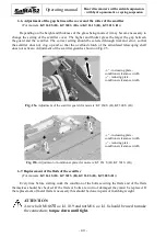
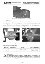
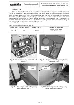
lift the support leg S (Fig. 9),
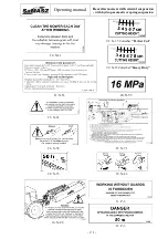
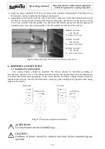
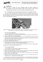
the mower is equipped with service-free transport lock (Fig. 13). Non-locking the lock may
cause damage to PTO shafts,
lift the 3-point linkage frame vertically with hydraulic cylinder and lock the lock Z (Fig. 11),
Fig. 11. Z – Locking bar
Z


