background image

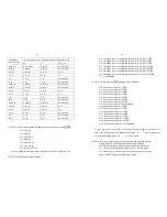
    Hold these two buttons to show firmware version; A/D code or input 
 

working voltage of indicator.   


(6)                            +   


Hold these two buttons to enter setting mode when the sealed calibration 


switch is on.   


(7)                          +   


Hold these two buttons to enter calibration mode when the sealed 


calibration switch is on.   


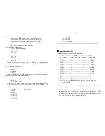
3.3 In setting mode: 
 
 
      HOLD  

UNITS     TARE 

OFF/ON 


(1) 

Rotate the flashed position from right to left 


(2) 

Change the digit on flashed position. The digit can be 
changed to 0, 1, 2…9; and be flashed. 


(3) 

Confirm receiving and storing the displayed parameters, 

                 After the setting of the last parameter, the indicator will  
            not exit the setup mode, and cycles from the first parameters for       
 

  viewing or modifications. 


(4) 

Exit from setting mode to normal work mode 


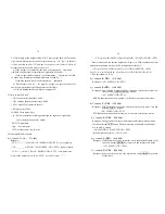
3.4 In displaying A/D code or input voltage mode: 


OFF 

UNIT

OFF 

TARE


 WT 

 VOL

FLT 

EXT


(1)                          No function 


(2)   


Choose the weight inner code or input working voltage to   


be displayed. The working voltage range is 4.8V-8V. If the 


voltage is not within range, it may damage the indicator.


Voltage value is shown like this “U x.xx” and its unit is V.   


(3)   


When A/D code of weight is shown, press this button to 


choose filtered or un-filtered weight A/D data; when 

X

 is


on, the data is filtered. 


(4)   


Press this button to exit this mode, and auto-reset the    


indicator, display all segments of LCD, full capacity…   


just like power on again and then it goes back to normal weighing mode.   


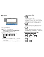
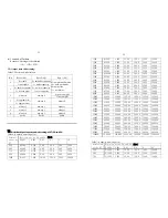
3.5 Calibration mode 
 
 
      HOLD  

UNITS     TARE 

OFF/ON 

 
(1)             Rotate the flashed position from right to left 
 
(2) 


   Change the digit on flashed position. The digit can be        


      changed to 0, 1, 2…9; and be flashed. 

 
(3) 


Confirm receiving input data and go into next 


 step. 

                                   
(4) 


    Exit from calibration mode to normal work mode 


.


CALIBRATION:


Before calibrate the scale, you should prepare a standard weight (more than 

25% of FS weight, and the unit is same as P10 setting) for calibration.   

1. 

Move away any weight on scale. When normal weighing mode, press and 

WT 


VOL

FLT

EXT

X


Содержание LPS-400

Страница 1: ...LPS 400 SCALE Operation Manual Contents subject to change without notice Version 1 0 2006 07 26...

Страница 2: ...aux appareils num riques de la Classe A prescrites dans le R glement sur le brouillage radio lectrique edict par le minist re des Communications du Canada Warnings Electrical installation For your pro...

Страница 3: ...radio computer or other electronic device These devices emit RF and can cause unstable scale readings If your scale ever performs poorly try moving the scale to a different room or location Avoid usi...

Страница 4: ...below 4 7V and you should replace batteries immediately 2 AC Adapter 6VDC 500mA with central negative 3 Work current 25mA when voltage in 5Vdc 8Vdc and not include load cell s consumption OPERATION T...

Страница 5: ...b oz Note The weighing units that can be used are restricted by display division and calibration weight unit restricted by P8 P9 and P10 For example if the calibration unit is kg calibration display r...

Страница 6: ...r input working voltage to be displayed The working voltage range is 4 8V 8V If the voltage is not within range it may damage the indicator Voltage value is shown like this U x xx and its unit is V 3...

Страница 7: ...le will be calibrated on second calibration point The default standard weight is 50 FS and at the same you can press ON OFF ZERO to exit the calibration mode Or load 12 5 100 FS weight and use PRINT H...

Страница 8: ...the A D data for loaded weight If the ADC increase for full capacity is NFS the power on zero range is set to Zp FS P12 setting and zero key range is set to Zk FS P13 setting Then proper ADC data of z...

Страница 9: ...thin the setting range 3 50d the weight reading will remain unchangeable 11 5 4 P4 x RS232 mode setting x 0 No RS232 function It will not transmit or receive any data although the scale is with RS232...

Страница 10: ...cimal digits x10 3 x 4 four decimal digits x10 4 x 5 no decimal point x10 1 5 10 P10 x Calibration unit x 0 kg as calibration unit x 1 lb as calibration unit As per the setting of P8 P9 and P10 follow...

Страница 11: ...zero point CAL P0 5 FS x 3 the range is set to calibration zero point CAL P0 10 FS x 4 the range is set to calibration zero point CAL P0 20 FS x 5 the range is set to calibration zero point CAL P0 50...

Страница 12: ...1d 9d If the variety of weight reading is within the setting range continuously for several times the scale is recognized as stable The normal setting is 1d 3d 5 19 P19 x Overload range that can be di...

Страница 13: ...u2 CR LF H1H2H3 CR ETX zero point error Note If the weight unit is lb oz U1U2 oz in above item 19 LF p w1w2w3w4w5w6 dp w7u1u2 CR LF H1H2H3 CR ETX Scale is stable and the current weight unit is kg or l...

Страница 14: ...400 24000 2500 0 2500 2 500 25 00 250 0 2500 25000 3000 0 30000 3 000 30 00 300 0 3000 30000 3500 0 3500 3 500 35 00 350 0 3500 35000 4000 0 4000 4 000 40 00 400 0 4000 40000 5000 0 5000 5 000 50 00 5...

Страница 15: ...500 25 00 250 0 2500 25000 600 0 3000 3 000 30 00 300 0 3000 30000 23 750 0 3750 3 750 37 50 375 0 3750 37500 800 0 4000 4 000 40 00 400 0 4000 40000 1000 0 5000 5 000 50 00 500 0 5000 50000 1200 0 6...

Страница 16: ...ition summary KEY MODE DEFINITION Normal weighing mode Enter or exit HOLD mode output the data as per P4 P5 P6 setting Setup mode Calibration mode Shift the flashed position from right to left HOLD PR...

Страница 17: ...00 31 7 Resolution select 500 600 750 800 1000 1200 1500 2000 2400 2500 3000 3500 4000 5000 6000 7000 7500 8000 10000 12000 15000 20000 25000 30000 35000 40000 50000 60000 70000 75000 80000 100000 P8...

Страница 18: ...2 3 2 Data filter intensity 0 very weak 1 weak 2 middle 3 strong P18 x 0 1 9 1 Check weight stability range 0 0 5d 1 1d 2 1 5d 3 2d 4 3d 5 4d 6 5d 7 6d 8 7d 9 8d P19 x 0 1 9 3 Overload limit range 0...

Отзывы: