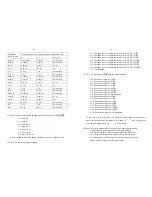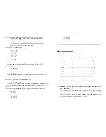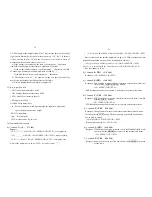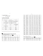
5.15) P15.x: select which zero point will be used when powered on and
weight
signal
is
NOT
within the power-on zero-point range:
x=0: Choose current weight as current power-on zero point.
x=1: Choose calibration zero point as power-on zero point
x=3: Choose power-off zero-point as power-on zero point, and
power-off tare weight as current tare weight.
5.16) P16.x: Zero tracking range
x=0: 0d, means no tracking
x=1:
+0.25d
x=2:
+0.5d
x=3:
+1d
x=4:
+1.5d
x=5:
+2d
x=6:
+3d
x=7:
+4d
x=8: +5d
Choose the zero tracking range as per the stability of weighing system,
accuracy and weight excursion. The normal setting is +0.5d ~ +1.5d.
5.17) P17.x: Data filter intensity
x=0
very
weak
x=1
weak
x=2
middle
x=3
strong
The larger the chosen digit is, data filter intensity is stronger, and the speed
of data updating is lower. The normal setting is 2.
5.18) P18.x: Range of weight stability checking
x=0:
+0.5d
x=1…9:
+1d --- +9d
If the variety of weight reading is within the setting range continuously for
several times, the scale is recognized as stable. The normal setting
is
+1d ~ +3d.
5.19) P19.x: Overload range that can be displayed (when weight is lager than
range, “
ˉˉˉˉˉ
”will be shown):
x=0:
S+0d
x=1:
FS+9d
x=2:
101%FS
x=3:
102%FS
x=4:
105%FS
x=5:
110%FS
17
x=6:
120%FS
x=7:
150%FS
x=8:
200%FS
x=9:
No
limitation
========================================================
Ⅵ
. The detail about RS232:
1. RS-232 connects between scale and Host:
Scale -----------------------Cable---------------------------Host
(DB9 female)--------(DB9 male)----(DB9 female)--------(DB9 male)
TXD 2 --------------- 2 ------------------------ 2 --------------2 RXD
RXD 3 --------------- 3 ------------------------ 3 --------------3 TXD
GND 5 --------------- 5 ------------------------ 5 --------------5 GND
DSR 4 --------------- 4 ------------------------- 4 --------------4 DTR
DTR 6 --------------- 6 ------------------------- 6 --------------6 DSR
CTS 7 --------------- 7 -------------------------- 7 --------------7 RTS
RTS 8 --------------- 8 -------------------------- 8 --------------8 CTS
NC 1 -------------- 1 -------------------------- 1 --------------1
NC 9 -------------- 9 -------------------------- 9 --------------9
Note: The indicator DB9 female’s pin4 and pin6 is shorted, pin7 and
pin8
is
shorted!
2. When P4 is set to 7: the protocol of RS232 is compatible to with NCI-SP1,
here is the details:
2.1) The baud rate and data format is fixed as per P5 and P6 setting.
Responses to serial commands will be immediate, or within one weight
measure cycle of the scale. One second should be more than adequate for use
as a time-out value by remote (controlling) device.
18


