


12
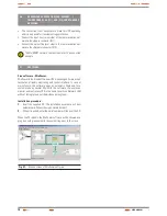
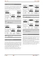
3.1.4. Control panel.
SELECT
button
ENTER
button
OFF
button
LCD
panel
ON / Alarm
silencer
button
Control panel. Tower type model.
fig. 16.
Button
function
ON button
By pressing the ON button, the UPS starts up, the acoustic
alarm is deactivated and it is done a battery test.
Off button
By pressing the OFF button, the UPS goes to bypass
mode and the inverter is shutdown. From now on, if the
bypass and mains are active, the output terminals supply
voltage through themselves.
SELECT button
The output voltage, frequency and the bypass enabling/
disabling can be selected if the UPS is on bypass mode
and by pressing the SELECT button and confirming by
pressing ENTER.
ENTER button
Table 3.
Functions of each button.
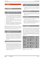
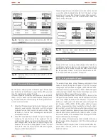
Bypass operating information
Inverter operating infor-
mation
Output
informa-
tion
Load infor-
mation
Battery infor-
mation
Information
of the Mode/
Fault/War-
ning codes
Information to select the output voltage
and frequency and the bypass enabling
and disabling
Input infor-
mation
LCD panel description
fig. 17.
Display
function
Input information
V
AC
It displays the input voltage value, which will be showed
from 0 to 999 Vac
hz
It displays the frequency value of the input voltage, which
will be showed from 0 to 99 Hz
h
It displays that the input voltage is higher than the SPEC
range and the UPS runs on battery mode.
L
It displays that the input voltage is lower than the SPEC
range and the UPS runs on battery mode.
Output information
V
AC
It displays the output voltage value, which will be showed
from 0 to 999 Vac.
hz
It displays the frequency value of the output voltage, which
will be showed from 0 to 99 Hz.
Load information
It displays the % of the load in W or VA, the maximum value
will be showed from 0 to 199% only.
ShORT
It displays that the output is short-circuited and the UPS
could be shutdown.
OVERLOAD
It displays that the load overcomes the SPEC range.
Battery information
V
DC
It displays the battery voltage value, which will be showed
from 0 to 999 Vdc.
It displays the % of the battery capacity, which will be
showed from 0 to 199%
OVER ChARGE
It displays that the battery is overcharged, and the UPS
could transfer to battery mode.
LOW
It displays that the battery is low and the UPS could be
shutdown shortly.
Information of Mode/fault/Warning codes
It displays the UPS operating mode. It will show the Mode/
Fault/Warning codes, which are identified in table 8 of
chapter 5.
Inverter operating information
It displays that the inverter is running.
Bypass operating information
It displays that the bypass is activated.
Information of output voltage and frequency and bypass enabling /
disabling
110V
AC
, 115V
AC
,
120V
AC
, 127V
AC
208V
AC
, 220V
AC
,
230V
AC
, 240V
AC
They are the eight selectable output voltage values with
the UPS on standby or bypass mode. One of them can be
activated at the same time only..
50 hz
60 hz
They are the two selectable frequency values of the output
voltage with the UPS on standby or bypass mode. One of
them can be activated at the same time only.
Bypass disable
Bypass enable
Selection of bypass enabled/disabled with the UPS on
standby or bypass mode. One of them can be activated at
the same time only.
Table 4.
LCD panel messages and their functions
USER MANUAL
Содержание SLC TWIN series
Страница 3: ......
Страница 29: ...28 NOTES USER MANUAL...
Страница 30: ...29 SALICRU NOTES...
Страница 31: ...30 NOTES USER MANUAL...
Страница 32: ......
Страница 35: ......
Страница 60: ......