background image

39

Log In

Home

Load

2020-09-15
07:28:06

L1

  231. 8

L2

  233. 5

L3

  232. 8

L1

  229. 6

L2

  229. 4

L3

  230. 1

L1

  0. 2%

L2

  1. 0%

L3

  0. 2%

Tot  

0. 2%

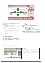
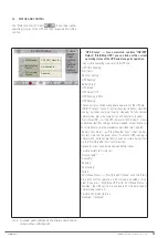
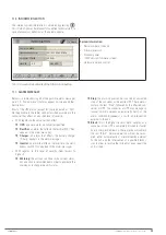
Fig. 35. 

Main screen in bypass mode. The power flow 

goes directly from the bypass input to the output, 

via the static bypass switch. The rectifier and 

charger continue operating.

The unit is now in bypass operating mode, described in 

4.5.3

.

6.1.5.  Procedure for transferring to normal mode from 

bypass mode

Based on the situation described in 

6.1.4

 (manual forced bypass 

mode), you can recover the normal operating mode of the UPS 

via manual command.
By accessing the "Status and Control", you can see that the 

"UPS Status" shows "Rectif. Running". To switch to bypass 

mode, you need to:

1. 

Press the "Status and Control" icon


 You are 

on the screen described in 

7.4

.

2. 

Press the "INV/BYP Output" icon


3. 

The "Output Control" pop-up box appears, with the "In-

verter" and "Bypass" options. Press "Inverter".

4. 

The inverter should restart, and you will recover the 

normal operating mode of the UPS. 

"UPS Status" should 

show "UPS Running", and on the main screen, the power 

flow will correspond to the one shown in 

Fig. 33

.

6.2.  PROCEDURE FOR STOPPING THE UPS

This section describes the correct procedure for complete shut-

down of the UPS, leaving the loads without power, and the UPS 

without any voltage at any of its input and output terminals 

(and batteries, if any).
This procedure may be necessary in interventions to change the 

installation, remove the UPS, replace it, etc.
With the UPS operating in normal mode (synoptic shown in 

Fig. 33

, and in the "Status and Control" submenu you can see 

that the "UPS Status" shows "UPS Running"), in order to shut it 

down completely, proceed as follows:

1. 

Stop the loads (or set their switches on the distribu-

tion board to "Off", if any) progressively.

2. 

Press the "Status and Control" icon


 You are 

on the screen described in 

7.4

.

3. 

Press the "Start/Stop UPS" icon


4. 

The "UPS Control" pop-up box appears, with the "Start" 

and "Stop" options. Press "Stop".

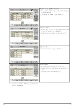
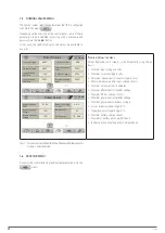
Fig. 36. 

"UPS Control" pop-up window. Press "Stop".

5. 

You can check the status on "Stand-By" of the UPS

The "UPS Status" field (Status and Control" submenu, see 

7.4

) shows:

Stand-By

On the main screen, you can also check that the power flow 

corresponds to that of the UPS when stopped, as shown in 

Fig. 37

.

Log In

Home

Load

2020-09-15
07:28:06

L1

  231. 8

L2

  233. 5

L3

  232. 8

L1

  229. 6

L2

  229. 4

L3

  230. 1

L1

  0. 2%

L2

  1. 0%

L3

  0. 2%

Tot  

0. 2%

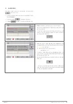
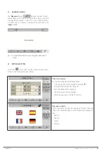
Fig. 37. 

Main screen with the UPS stopped. The power 

flow goes directly from the bypass input to the 

output, via the static bypass switch, and all con-

verters are stopped.

6. 

Set the switch corresponding to the UPS output on 

the control panel (external) to "Off".

7. 

Set the output switch of the UPS to "Off" (

Q2

). 

8. 

Disconnect the batteries:

a. 

Units with internal batteries:

 disconnect the 3-pole 

battery connector (

Fig. 1 

Detail A

on the front), or set 

the battery switch to "Off" (

Q6

, on the front), as appli-

cable.

b. 

Units with external batteries:


disconnect the 3-pole 

battery connector (

Fig. 3 and Fig. 4 for 30 kVA and 40 

kVA units, 

on the back), or set the battery switch to 

"Off" (

Q3, 

Fig. 7 and Fig. 8 for 50 kVA, 60 kVA and 80 

kVA units, 

on the front), as applicable. Also, set the ex-

ternal battery cabinet switch to "Off" 

(Q8

,

 Fig. 10 and 

Fig. 11).

c. 

Units with shared internal and external batteries:


carry out points 

a.

 and 

b.

 described above one after 

the other.

9. 

Set the switch corresponding to the UPS input on the 

control panel (external) to "Off".

 If there is a separate 

bypass line for the UPS, also set this switch on the control 

panel to "Off".

SLC CUBE4

  - UNINTERRUPTIBLE POWER SUPPLY SYSTEM 

-

USER MANUAL        

Содержание SLC CUBE4

Страница 1: ...30 80 kVA USER MANUAL...

Страница 2: ...bilisation and considerations 5 1 5 1 Siting for single units 5 1 5 2 Siting for parallel systems 5 1 5 3 Immobilisation and levelling of the unit 5 1 5 4 Preliminary considerations before connection...

Страница 3: ...NICAL SERVICES NETWORK 9 ANNEX I TECHNICAL SPECIFICATIONS 9 1 INTERNATIONAL STANDARDS 9 2 ENVIRONMENTAL CHARACTERISTICS 9 3 MECHANICAL CHARACTERISTICS 9 4 ELECTRICAL CHARACTERISTICS 9 4 1 Electrical c...

Страница 4: ...r omissions that may be present The images included in this document are for illustrative purposes only and may not accurately represent the parts of the unit shown in this manual therefore they are n...

Страница 5: ...e they may refer interchangeably to the UPS itself or to the UPS and the bat teries regardless of whether it is assembled in the same metal enclosure box or not Batteries or capacitor banks A group or...

Страница 6: ...is is a product for commer cial and industrial application in the second environment installation restrictions or additional measures may be necessary to avoid disturbances This unit is not suitable f...

Страница 7: ...er that is 1654 mm high for 50 kVA 60 kVA and 80 kVA units Fig 1 to Fig 9 show front and rear views and their constituent parts LCD synoptic Internal battery connec tors see Detail A Battery boxes Whe...

Страница 8: ...e slot Digital inputs outputs see Detail B SNMP NIMBUS slot Parallel ports RJ45 Output circuit breaker Q2 Output terminals U V W N Earth terminal Input terminals R S T N Cable gland Manual bypass swit...

Страница 9: ...inals U V W N Earth terminal Input terminals R S T N Separatebypassterminals R S T N Cable gland Manualbypassswitch with mechanicallock Q5 Separate bypass circuit breaker Q4 R S T N INPUT R S T N BYPA...

Страница 10: ...put circuit breaker Q2 Output terminals U V W N Earth terminal Input terminals R S T N Separatebypassterminals R S T N Cable gland Manualbypassswitch with mechanicallock Q5 Separate bypass circuit bre...

Страница 11: ...h Q6 Manual bypass switch with mechanical lock Q5 Output circuit breaker Q2 Output terminals U V W N Input terminals R S T N Earth terminal Options SNMP RS232 RS485 USB AS400 relay extension Remote ba...

Страница 12: ...h Q1 Internal battery discon nect switch Q6 Manual bypass switch with mechanical lock Q5 Output circuit breaker Q2 Output terminals U V W N Input terminals R S T N Earth terminal Options SNMP RS232 RS...

Страница 13: ...mechanical lock Q5 Output circuit breaker Q2 Output terminals U V W N Battery terminals N Input terminals R S T N Separate bypass terminals R S T N R S T N INPUT R S T N BYPASSINDEPENDIENTE U V W N SA...

Страница 14: ...n B1 Q3 battery disconnect switch Separate bypass dis connect switch Q4 Manual bypass switch with mechanical lock Q5 Output circuit breaker Q2 Output terminals U V W N Battery terminals N Input termin...

Страница 15: ...rallel ports Slot 1 SNMP NIMBUS Slot 2 free Bat Temp Contacts Amb Temp Contacts Detail C Digital inputs Digital outputs Fig 9 Detailed view of the external interface and commu nications SLC CUBE4 UNIN...

Страница 16: ...n for these power ratings depth x width x height 851 x 570 x 1008 mm for 30 kVA and 40 kVA units and 851 x 678 x 1654 mm for 50 kVA 60 kVA and 80 kVA units see Fig 10 and Fig 11 Temp probe Battery dis...

Страница 17: ...i Battery disconnect switch Q8 Earth Fig 11 Front view with the door open and closed of the 1654 mm battery cabinet for 50 kVA 60 kVA and 80 kVA standard units SLC CUBE4 UNINTERRUPTIBLE POWER SUPPLY S...

Страница 18: ...cabinet T Top cable entry B Separate bypass line only for I I III III units SB UPS without bypass line L Input output single phase single phase configuration MB Input output single phase three phase c...

Страница 19: ...the UPS international standard IEC 62040 3 corresponding to VFI SS 111 1 The UPS achieves maximum performance in terms of efficiency reliability availability and adaptability to the needs of every in...

Страница 20: ...f the input voltage isolated from potential disturbances peaks dips unstable frequency etc The architecture of this converter is based on 3 separate single phase inverters with 3 switching levels 4 IG...

Страница 21: ...line can be or dered manually or it can be activated by the UPS automatic con trol in certain emergency situations As power switching elements it uses thyristors SCR and re lays Thyristors for connec...

Страница 22: ...event of an AC power supply fault the rectifier booster switches its input power source from the AC network to the battery without interruption The battery voltage decreases ac cording to the dischar...

Страница 23: ...ternal converter Manual bypass activation MANUAL BYPASS AC OUTPUT BYPASS STATIC SWITCH INVERTER BATTERY CHARGER DC LINK BATTERY PACK RECTIFIER BOOSTER BYPASS LINE AC INPUT Fig 16 UPS power flow in byp...

Страница 24: ...by configuration the unit supplies a fixed output frequency of 50 or 60 Hz which may be different to the input frequency It consists of an operating mode derived from normal mode as double conversion...

Страница 25: ...ifier AC input line switch common to the bypass line if it is not a unit with an optional separate bypass this switch is a circuit breaker for models up to 50 kVA and a disconnect switch for 80 kVA an...

Страница 26: ...ambient temperature 3 Direct communications of the unit USB Type B port Modbus protocol for user and ser vice software for qualified staff RS232 RS485 port DB9 connector Modbus protocol for user physi...

Страница 27: ...the references on the delivery note It has not suffered any mishap during transport pack aging and impact indicator in perfect condition Otherwise follow the protocol indicated on the label at tached...

Страница 28: ...Transport to the site If the reception area is far from the installation site it is recommended to move the SLC CUBE4 using a pallet truck or another more suitable means of transport assessing the dis...

Страница 29: ...cabinet Fig 24 Minimum peripheral dimensions for ventilating the UPS C B A A A Ax2 Ax2 Ax2 A A A Battery cabinet UPS n 1 Battery cabinet UPS n 2 UPS cabinet n 1 UPS cabinet n 2 UPS cabinet n 3 UPS cab...

Страница 30: ...taller provide and in stall this external board paying attention to the version and configuration of the unit or system available and to the documentation on the pen drive relating to the Recom mended...

Страница 31: ...user For 50 kVA 60 kVA and 80 kVA units the internal battery protection consists of a disconnect switch fuses Q6 see Fig 5 and Fig 6 Units from group b 1 For 30 kVA and 40 kVA units the internal batt...

Страница 32: ...h UPS of a parallel system In the documentation supplied with this user manual and oronyourpendrive thereisinformationrelatingto the Recommended installation for each input and output con figuration I...

Страница 33: ...Connect this conductor to the earth terminal before supplying voltage to the input terminals The original factory battery circuit type is open Do not handle the battery connectors and or the dis conne...

Страница 34: ...s line COM consists of a very low voltage cir cuit and it must be installed separately from other lines that carry dangerous voltages power distribution line 5 2 6 1 Digital inputs relay interface and...

Страница 35: ...see manual EL139 00 and the other is free to allow the inclusion of an SNMP electronic unit or another optional ad dition The aforementioned slots are located on the back of the unit at the top in hor...

Страница 36: ...xiliary contact of the maintenance by pass switch and the auxiliary contact of the output switch for parallel systems to the corresponding connector of the unit The earth cable is connected correctly...

Страница 37: ...o On If there is a separate bypass line for the UPS also set this switch on the control panel to On 3 Set the input switch of the UPS to On Q1 If the main menu icon flashes red and you hear an acousti...

Страница 38: ...d to On if any progressively 14 The system is operating fully and the loads are pro tected by the UPS You can obtain basic information on the main screen of the control panel synoptic input and output...

Страница 39: ...1 Stop the loads or set their switches on the distribu tion board to Off if any progressively 2 Press the Status and Control icon You are on the screen described in 7 4 3 Press the Start Stop UPS icon...

Страница 40: ...e installation To switch to maintenance bypass mode 1 Press the Status and Control icon You are on the screen described in 7 4 2 Press the Start Stop UPS icon 3 The UPS Control pop up box appears with...

Страница 41: ...nal battery cables on the back of 30 kVA and 40 kVA units as applicable Also set the external battery cabinet switch to On Q8 c Units with shared internal and external batteries carry out points a and...

Страница 42: ...ace the wire bridge or set the remote button that replaced this bridge to Off b From here proceed as described in 6 1 3 Generic start up procedure normal mode and ignore the fol lowing steps described...

Страница 43: ...information in area 1 with certain specificities will always be acces sible from any screen The buttons and icons in areas 1 and 4 which are always visible are described in the table below 7 1 MAIN OR...

Страница 44: ...on indicates that the Nimbus card is correctly inserted into its slot and is connected to the Internet Ifthisiconappearscrossedout itmayindicatethattheNimbuscardisnotpresent orthereisnoInternetaccess...

Страница 45: ...of a dynamic power flow in blue will detail the UPS operating mode normal mode bypass mode battery mode etc 7 2 MEASUREMENTS MENU By pressing the Measurements menu icon you ac cess the set of measure...

Страница 46: ...positive and negative bank battery tem perature and autonomy time estimate 1 2 Battery currents positive bank and negative bank 2 2 Home Input Rec Inv Batteries Bypass Output Voltage Frequency 231 7V...

Страница 47: ...ional page s of alarms which you can browse with the arrows Maintenance Byp Closed Rec V Bat out of margin UPS Unit on Bypass Rec Low Battery When new alarms appear pending acknowledgement they are re...

Страница 48: ...no shown above and the page are on the right hand side of the screen The information for each event consists of Event Number ID from 1 to 500 Description of the Event Date and Time DD MM YYYY HH MM In...

Страница 49: ...er normal mode press the same button and transfer to inverter Start Stop UPS start the UPS normal or ECO mode or stop it completely rectifier charger inverter stopped output in bypass For more details...

Страница 50: ...Bypass Voltage PhN Bat Number Bat Capacity 230V 15 12 3 6A 22 18 0Ah Nominal Values submenu Values displayed on 2 screens scroll horizontally using the ar rows Nominal input voltage in volts Nominal...

Страница 51: ...settings Date Time Date Time September 7 36 15 2020 Hour Day Year Minute Month Home Language Brightness Comm Date Time Date Time submenu Any user can configure the following fields Time drop down nume...

Страница 52: ...ptions Even Odd and No Parity Stop bits drop down numeric keypad values of 0 2 bits Protocol pop up menu with the options Modbus and Shell Tab 8 Submenus and screens of the Settings menu 7 9 HELP BUTT...

Страница 53: ...e Charger an alarm that affects the battery charger Charg appears in the alarm message Inverter an alarm that affects the inverter or the static bypass switch Inv appears in the alarm message With reg...

Страница 54: ...se T not present Rec Phase Rotation Rectifier input phase rotation Rec Vin Sync failure Rectifier input network synchronisation fault Rec Low Battery Low battery warning Rec V Bat out of margins Recti...

Страница 55: ...Inverter stop due to overload Inv Stop Desat IGBT R Maximum inverter IGBT desaturations phase R Inv Stop Desat IGBT S Maximum inverter IGBT desaturations phase S Inv Stop Desat IGBT T Maximum inverte...

Страница 56: ...ting Time Inv Block Vout Failure Inverter blocked due to Output Voltage Fault Inv Block SSByp R short Inverter blocked due to short circuited static bypass switch phase R Inv Block SSByp S short Inver...

Страница 57: ...ypass UPS ECO mode in Inverter The UPS is in ECO mode output in inverter UPS on back up mode UPS in autonomy or battery mode UPS Charging Batteries UPS charging batteries Inv Out Current Limit Output...

Страница 58: ...ed out by the T S S except for the replacement of batteries which can also be carried out by qualified staff who are familiar with them No other person should handle them Depending on the UPS configur...

Страница 59: ...UPS 0 35 Battery Tab 14 Environmental characteristics 9 3 MECHANICAL CHARACTERISTICS Cabinet specifications 30 kVA 40 kVA 50 kVA 60 kVA 80 kVA Dimensions Depth Width Height 909 x 377 x 1042 mm 919 x...

Страница 60: ...NiCd Battery charger bus voltage Configurable between 180 330 V Charge time 5 hours 90 capacity Floating voltage at 20 C 13 65 V battery programmable between 1 3 V 14 V Voltage compensation depending...

Страница 61: ...2 USB Expansion slot 1 NIMBUS card Expansion slot 2 Free slot Digital inputs 4 inputs Relay interface 4 programmable relays Protocol MODBUS RTU Display 5 touchscreen EPO function 2 pole normally close...

Страница 62: ...notifications to the Technical Service response time is minimized to the maximum To know if the unit is connected and sending data to the cloud the following icon should appear on the right at the top...

Страница 63: ...not have an account you must register in order to access the unit Once registered or if you already have a SALICRU account you must log in Once you have accessed your account the next step is to regi...

Страница 64: ...nical characteristics of the NIMBUS card are shown below Characteristic Processor Sitara AM3358BZCZ100 1 GHz 2000 MIPS Graphics card SGX530 3D 20M Polygons S SDRAM memory 512 MB DDR3L 800 MHZ Flash me...

Страница 65: ...presentation formed by 2 transparent conductive layers and a special crystalline material in the middle liquid crystal which have the ability to orientate light as it passes through LED Light emitting...

Страница 66: ...66 SALICRU...

Страница 67: ...67 SLC CUBE4 UNINTERRUPTIBLE POWER SUPPLY SYSTEM USER MANUAL...

Страница 68: ...68 SALICRU...

Страница 69: ...69 SLC CUBE4 UNINTERRUPTIBLE POWER SUPPLY SYSTEM USER MANUAL...

Страница 70: ...da de la Serra 100 08460 Palautordera BARCELONA Tel 34 93 848 24 00 Fax 34 93 848 22 05 sst salicru com SALICRU COM www linkedin com company salicru salicru_SA Product Range Uninterruptible Power Supp...

Отзывы: