34
SALICRU
T
+ N –
T
+ N –
T
+ N –
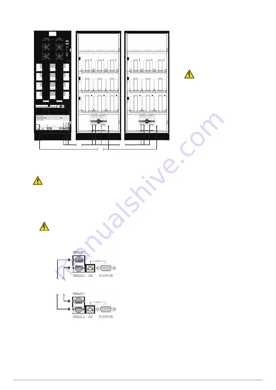
Fig. 29.
Connection between the UPS and two battery
cabinets.
Danger of electric shock
. If, after start-up of the UPS,
the battery cabinet must be disconnected, a complete
shutdown of the unit must be performed. Open the battery dis-
connect switch in the battery cabinet and/or switch located in
the UPS. Wait at least 5 min. until the filter capacitors have
discharged.
5.2.5. Connection of the parallel bus
•
The communications line (COM) consists of a very
low voltage safety circuit.
To ensure the quality, it must be installed separately from
other lines that carry dangerous voltages (power distribution
line).
Parallel connection bus
UPS nº 1
•••
•••
UPS nº «N»
Fig. 30.
RJ45 connectors of the parallel communication bus.
•
Parallel connection bus
. Use the Ethernet cable with
RJ-45 connectors on both ends to connect up to 16 SLC
CUBE4 units. The parallel bus loop must be closed.
•
In addition to the communications bus, the
parallel system installation must be equipped
with a board that has individual input and output
protection devices, as well as a manual bypass
with mechanical lock.
5.2.6. Interface and communications
•
The communications line (COM)
consists of a very low voltage cir-
cuit and it must be installed separately from
other lines that carry dangerous voltages (power
distribution line).
5.2.6.1. Digital inputs, relay interface and
communications
The
SLC CUBE4
series UPS feature the fol-
lowing connections for communication with ex-
ternal peripherals of the unit or other identical
units:
•
Four digital inputs via terminal strip.
•
Four relay interface outputs via terminal strip.
•
Communication via RS232/RS485 (subD9)
ports or USB.
•
2 ports for parallel communication.
•
Two slots for integrating an SNMP card (slot1) or free slot
(slot2), with the latter being suitable for housing the following,
optionally:
SNMP.
RS232, RS485, USB.
AS400 (relay extension).
Remote battery temperature.
All connectors related to communications are located grouped
on the interface panel and are accessible from the bypass
module after removing the cover that conceals them entirely.
The communication interface has the following connections via
the terminal strip:
•
Temperature sensor input.
BATT: sensor for compensating the battery floating
voltage. Parameter shown on the control panel screen.
AMBT: sensor for measuring the ambient temperature.
Parameter shown on the control panel screen.
•
External EPO button signal input.
•
4 programmable digital inputs (see
Table 2
).
•
4 programmable relay outputs (see
Table 2
).
Содержание SLC CUBE4
Страница 1: ...30 80 kVA USER MANUAL...
Страница 66: ...66 SALICRU...
Страница 67: ...67 SLC CUBE4 UNINTERRUPTIBLE POWER SUPPLY SYSTEM USER MANUAL...
Страница 68: ...68 SALICRU...
Страница 69: ...69 SLC CUBE4 UNINTERRUPTIBLE POWER SUPPLY SYSTEM USER MANUAL...


