30
SALICRU
INPUT
OUTPUT
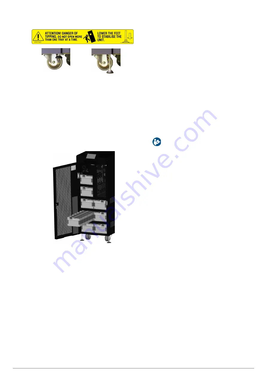
Fig. 26.
Stabilising elements for the unit/battery module.
• Unit and battery maintenance is the responsibility of the
T.S.S. or authorised staff.
The batteries are always accessed from the front on all
units and/or battery modules. When the batteries are lo-
cated inside the UPS cabinet, they can be removed in sets,
grouped into 11 units in plastic enclosures. For the small
external battery cabinet (1004 mm high, see
), the batteries
are also arranged in the same type of enclosure (see
Fig.
27).
Fig. 27. Detail of front access to the batteries. Example of 30
kVA and 40 kVA units.
In the case of the large external battery cabinet (1654 mm
high, see
Fig. 11
), the larger and heavier batteries are ar-
ranged in removable trays in sets of 3 units per tray. Before
any handling, observe the indications on the label attached
to each one.
5.1.5.4. Preliminary considerations before connection
• The
description of this manual refers to the connection of
terminals and switch operations that are only available in
certain versions or units with extended autonomy. Ignore
the related operations if your unit does not have them.
• Follow and observe the instructions described in this sec-
tion relating to the installation of a single unit or a parallel
system.
• Protection or external manual bypass board:
It is recommended to have an external manual bypass
panel provided with input, output, static bypass (the
latter only in the
SLC CUBE4 B
version) and manual
bypass protection devices in single installations.
For parallel systems of up to two units, it is highly rec-
ommended to have a protection board and it is essen-
tial for systems of 3 or more units. The switches on the
board must allow a UPS to be isolated from the system
in the event of an anomaly and the loads to be supplied
via the remaining ones, either during the period of pre-
ventive maintenance or during the fault and its repair.
• On request, it is possible to supply an external manual by-
pass panel for a single unit or a parallel system.
You can also choose to have the installer provide and in-
stall this external board, paying attention to the version
and configuration of the unit or system available and to the
documentation on the pen drive relating to the "Recom-
mended installation".
•
In the documentation supplied with this user
manual and/or on your pen drive, there is informa-
tion relating to the "Recommended installation" for each
input and output configuration. It shows the wiring dia-
grams, as well as the protection size and the minimum
cross-sections of the cables connected to the unit, ac-
cording to its nominal working voltage. All values are cal-
culated for total maximum cable length of 30 m between
the distribution board, unit and loads.
For longer lengths, correct the cross-sections to pre-
vent voltage drops, observing the regulations or stand-
ards of the country.
In the same documentation and for each configuration,
the information for "N" parallel units is available, as
well as the characteristics of the "Back-feed protec-
tion".
• In parallel systems, the length and cross-section of the ca-
bles that run from the protection board to each UPS and from
these to the board will be the same for all of them without
exception.
• The cross-section of the cables must always be considered
in relation to the size of the switch terminals, so that their
entire cross-section is correctly embraced for optimal con-
tact between the two elements.
• Only the nominal currents are printed on the unit's name plate,
as indicated in the EN-IEC 62040-1 safety standard. For the
input current calculation, the power factor and the unit's per-
formance have been considered.
• If peripheral input, output or bypass elements such as trans-
formers or autotransformers are added to the UPS or parallel
system, the currents indicated on the name plates of these
elements must be considered in order to use the appropriate
cross-sections, observing the local and/or national Low
Voltage Electrotechnical Regulations.
• When an isolation transformer is incorporated into a UPS or
parallel system, as standard, as an option or installed by you,
either at the input, bypass or output line or at all of them, pro-
tection devices against indirect contact (differential switch)
must be fitted at the output of each transformer, as due to its
Содержание SLC CUBE4
Страница 1: ...30 80 kVA USER MANUAL...
Страница 66: ...66 SALICRU...
Страница 67: ...67 SLC CUBE4 UNINTERRUPTIBLE POWER SUPPLY SYSTEM USER MANUAL...
Страница 68: ...68 SALICRU...
Страница 69: ...69 SLC CUBE4 UNINTERRUPTIBLE POWER SUPPLY SYSTEM USER MANUAL...


