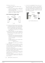
39
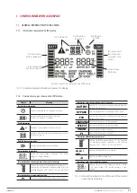
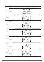
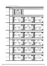
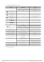
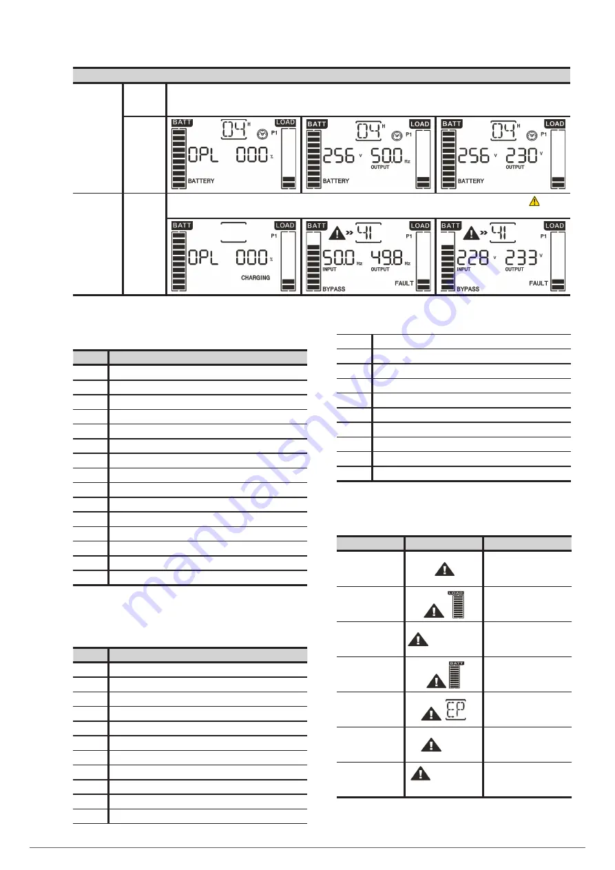
Operating mode / state
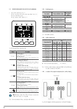
Battery test
Description.
With the UPS in AC mode or CF mode, press the ‘TEST
’
button for more than 0.5 seconds. The audible alarm will beep and the battery test
will start. In the electric flow diagram of the display, the line between I / P and the inverter icon flashes for information purposes. This test
is useful to check the battery state.
LCD display.
Error or fault
state
TWIN RT2
4-10kVA
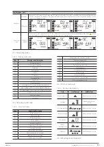
When an error or fault is detected in the UPS, the inverter will lock. The fault code will be displayed on the screen and the
icon will
illuminate. Table 13 shows the error or fault codes and the correlation with the description.
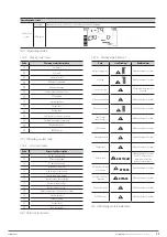
BYPASS
Tab. 19.
Operating modes.
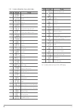
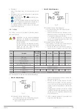
7.3.4.3. Warning or alert codes.
Code
Warning or alert description
01
Disconnected battery.
07
Overcharge in the battery.
08
Low battery.
09
Output overload.
0A
Fan fault.
0B
EPO activated.
0D
Overtemperature.
0E
Charger fault.
10
L1 input fuse open.
21
Line voltages of UPSs connected in parallel are different
22
Bypass voltages of UPSs connected in parallel are different
33
UPS locked in bypass after 3 successive overloads in 30 minutes
3A
Maintenance switch cover open
3D
Bypass not available
3E
Start-up fault
Tab. 20.
Warning or alert code.
7.3.4.4. Error or fault codes.
Code
Error or fault description
01
DC bus start-up fault.
02
DC bus overvoltage.
03
DC bus undervoltage.
04
DC bus imbalance.
11
Inverter soft start fault
12
High voltage in the inverter
13
Low voltage in the inverter
14
Inverter output short-circuited
1A
Negative power fault at the output.
21
Battery thyristor short-circuited.
24
Inverter relay short-circuited.
2A
Battery charger short-circuited at its output
31
CAN communication fault
35
Parallel cable fault
36
Parallel communication fault
41
Overtemperature
42
CPU communication fault
43
Output overload
6A
Battery start-up fault
6B
PFC current fault in battery mode
6C
DC Bus voltage change too fast
Tab. 21.
Error or fault code.
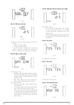
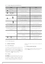
7.3.4.5. Warning or alert indicators.
Code
Icon (flashing)
Audible alarm
Battery voltage low.
Modulated every 1 seconds
Overload.
Modulated twice every 1
seconds
Disconnected battery.
BATT FAULT
Modulated every 1 seconds
Battery overcharge
Modulated every 1 seconds
EPO activated.
Modulated every 1 seconds
Fan fault /
Overtemperature
TEMP
Modulated every 1 seconds
Charger fault
CHARGING
BATTERY
Modulated every 1 seconds
Tab. 22.
Warning or alert indicators.
SLC TWIN PRO2
UNINTERRUPTIBLE POWER SUPPLY SYSTEMS (UPS)
USER MANUAL

