15
and install them to obtain two bases to hold the device and
the battery module.
•
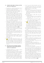
Place the UPS and battery module upright between the two
bases (see Fig. 7) and at a distance of 70 mm from each
end, similar to as shown in Fig. 7.
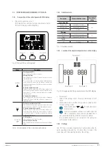
Fig. 7.
Vertically mounted tower-type model with backup
extension (battery module).
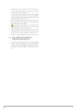
5.1.5.4. Mounting as a rack in a 19” cabinet.
•
To mount a device in a 19” rack cabinet, proceed as follows
Using the supplied screws, fix the two adapter angles
for use as handles on each side of the UPS, respecting
your hand.
To install the device in a rack cabinet, it is necessary
to have internal lateral guides for use as supports.
Alternatively, and upon request, we can supply
universal slides for use as guides, for installation by
the user.
Mount the guides at the required height, ensuring
correct tightening of the fixing screws and appropriate
fitting in the machining, according to each case.
Place the device onto the guides and insert it all the
way to the back.
Depending on the device model and weight, and/or
whether it is installed in the upper or lower part of the
cabinet, it is recommended that two people carry out
the installation operations.
Fix the UPS to the cabinet frame using the screws
supplied with the handles.
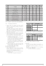
Fig. 6.
Vertical tower-type mounting.
5.1.5.3. Vertical tower-type mounting with backup extension
(battery module).
•
The description in this section refers to a device with a
single battery module. For a greater number, proceed in a
similar way.
•
Rotate the control panel according to section 5.1.5.1.
•
Take the 4 plastic pieces in the form of an angle supplied
with the UPS and the two supplied with the battery module,
SLC TWIN PRO2
UNINTERRUPTIBLE POWER SUPPLY SYSTEMS (UPS)
USER MANUAL


