27
7. CONTROL PANEL WITH LCD DISPLAY.
7.1. GENERAL INFORMATION FOR THE SERIES.
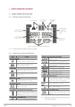
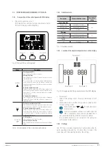
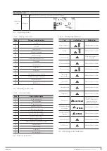
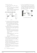
7.1.1. Information represented by the display.
Input voltage and
battery information
Fault information
Information about
battery charge level
Discharge time
information
Information about
the charge level
connected to the
output
Information about the operating mode of the device
Output voltage
information
Audible alarm
disabled
Fig. 21.
Graphic and textual information shown on the display.
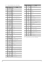
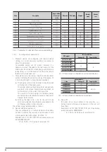
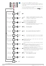
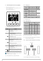
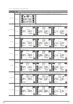
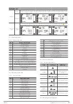
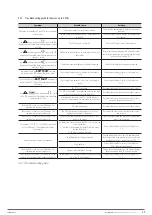
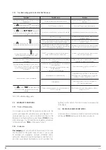
7.1.2. Common messages shown on the LCD display.
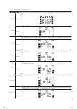
Display
Meaning
Backup time information.
Indicates the backup time in analogue clock mode.
Indicates the backup time in digital clock mode.
H - Hours, M - Minutes, S - Seconds.
Fault information.
Indicates as a warning that a fault has occurred.
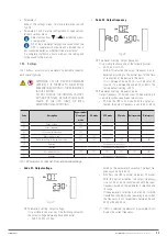
Indicates a numerical code from the settings menu shown in
Table 9 of Section 7.5.
Audible alarm information.
Indicates that the audible alarm is disabled.
Output voltage information.
Indicates the output voltage or frequency. V AC - Output
voltage, Hz - Output frequency.
Information about the charge level connected to the output.
Indicates the charge level connected to the output as a %,
by displaying four equivalent segments respectively in the
following proportion: 0-25 %, 26-50 %, 51-75 % and 76-100
%.
Information about programmable outputs
P1
Indicates that the programmable outputs are activated.
Information about the operating mode of the device.
BATTERY
Indicates that the device is supplying output voltage from
the battery (battery mode).
BYPASS
Indicates that the device is activated in BYPASS mode.
ECO
Indicates that the device is supplying output voltage from
the bypass (ECO mode).
CHARGING
Indicates that the device is in charging mode.
CF/CVCF
Indicates that the device is in converter mode.
ONLINE
Indicates that the inverter is working.
P1
Indicates that the output is activated.
Information about battery charge level.
Indicates the battery charge level as a %, by displaying
four equivalent segments respectively in the following
proportion: 0-25 %, 26-50 %, 51-75 % and 76-100 %.
BATT
FAULT
Indicates that the battery is not connected.
Indicates low battery voltage level.
Information about input and battery voltage.
Indicates the input voltage, frequency or battery voltage.
V AC - Input voltage, V DC - Battery voltage, Hz - Input
frequency.
Tab. 4.
Information shown on the LCD panel of the control
panel and its meaning.
SLC TWIN PRO2
UNINTERRUPTIBLE POWER SUPPLY SYSTEMS (UPS)
USER MANUAL


