26
SALICRU
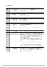
Indicator
State
Description
Inverter indicator
Steady green
Inverter is feeding the load
Flashing green Inverter is starting, or UPS is working in ECO mode
Steady red
At least one module’s inverter is failure, and inverter is not feeding the load
Flashing red
Inverter is feeding load, and at least one module’s inverter is failure
Off
Inverter is not working in all modules
Load indicator
Steady green
UPS output is on and is normal
Steady red
UPS output is overload and time is over, or output is shorten, or output has no power supply
Flashing red
UPS is overload
Off
No output voltage
Status indicator
Steady green
Normal operation
Steady red
Fault
Tabla 14.
Status Description of Indicator
There are two different types of audible alarm during UPS operation as shown in table.15.
Alarm
Purpose
Two short, one long
when system has general alarm (for example: main input abnormal), this audible alarm can be heard
Continuous alarm
When system has serious faults (for example: fuse or hardware fault), this audible alarm can be heard
Table 15.
Description of Audible Alarm
9.2. FUNCTIONAL KEYS
There are 4 functional buttons on operator control and display
panel, which are used together with LCD. The functions
description is shown in table. 16.
Funct. key
Functions
EPO
To shutdown the rectifier, inverter, static bypass
and battery
TAB
Select
ENTER
Confirm
ESC
Exit
Table 16.
Functions of Functional Keys
9.3. BATTERY PACK INDICATOR
The LED on the front panel of battery pack indicates battery pack
status. If battery fuse in battery pack is broken, LED changes
to be red. Customer must contact with our local distributer to
maintain it.
9.4. LCD DISPLAY TYPE
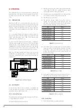
Following the self-check of UPS LCD display, the main LCD
display is shown as fig. 47, which can be divided into three
display windows: system information, data command and
current record.
Fig. 47.
Main LCD Display


