


21
7. INSTALLATION OF UPS RACK SYSTEM AND
PARALLEL SYSTEM
7.1. OVERVIEW
The single or parallel system should be installed according to
the installation procedures of the UPS rack module system and
the requirements in this Chapter.
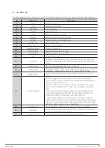
For single UPS rack module installation the EPO button on the
front panel of the UPS rack controls the emergency stop of UPS
modules and bypass static switch and also supports remote
emergency power off function that can be used to shut down
the UPS rack module remotely.
UPS1
Dry contact board GJ
J4-2
J4-3
UPS1
Dry contact board GJ
J4-2
J4-3
UPS2
Dry contact board GJ
J4-2
J4-3
Fig. 35.
Circuit diagram of EPO
7.2. UPS RACK MODULES IN PARALLEL SYSTEM
The basic installation procedures of parallel system are the
same with those of the UPS rack module system. In this section,
only the installation procedures related to the parallel system
are introduced.
7.2.1. Installation of Cabinet
To make the maintenance and system test easier, an external
maintenance bypass is recommended in the installation.
7.2.2. External Protective Devices
Refer to Chapter 4 Installation
7.2.3. Parallel Signal Board
Installation of parallel signal board
The parallel signal board BJ is installed at the rear of the static
switch power module. Refer to fig.36 and 37.
Fig. 36.
Installation of Parallel Signal Board BJ (a)
Fig. 37.
Installation of Parallel Signal Board BJ (b)
•
Remove cable W102 as fig. 36
•
Install parallel signal board BJ as fig.37
•
Connect cable 1 and cable 2 as fig.37
ADAPT
SISTEMA DE ALIMENTACIÓN ININTERRUMPIDA
MANUAL DE USUARIO


