25
9. OPERATOR CONTROL AND DISPLAY PANEL
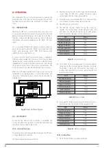
This chapter introduces the functions and operation instructions of the UPS operator control and display panel in detail, and provides
LCD display information, including LCD display types, detailed menu information, prompt window information and UPS alarm list.
Fig. 46.
UPS operator control and display panel
Indicator
Function
REC
Rectifier indicator
BAT
Battery indicator
BYP
Bypass indicator
INV
Inverter indicator
OUTPUT
Load indicator
STATUS
Status indicator
Table 12.
Description of UPS Display Panel indicators
Button
Function
EPO
EPO (emergency power off)
TAB
Select
ENTER
Confirm
ESC
Exit
Table 13.
Description of UPS Display Panel buttons
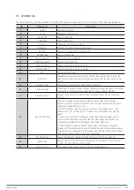
9.1. MIMIC CURRENT PATH
The LEDs shown on the mimic current path represent the various UPS power paths and show the current UPS operating status. The
status description of indicators is shown in table. 14.
Indicator
State
Description
Rectifier indicator
Steady green
Rectifier of all modules is normal
Flashing green At least one of module rectifier is starting
Steady red
At least one Rectifier of module fault
Flashing red
Main input of at least one module is abnormal
Off
Rectifier is not working
Battery indicator
Steady green
Battery is charging
Flashing green Battery is discharging
Steady red
Battery is abnormal (battery failure, no battery or battery reverse) or battery converter is
abnormal (failure, over current or over temperature) , EOD
Flashing red
Battery voltage is low
Off
Battery and battery converter is normal, battery is not charging
Bypass indicator
Steady green
UPS is working in bypass mode
Steady red
Bypass is failure
Flashing red
Bypass voltage is abnormal
Off
Bypass is normal and is not working
ADAPT
SISTEMA DE ALIMENTACIÓN ININTERRUMPIDA
MANUAL DE USUARIO


