background image

8. START UP

9. DEPRESSURISATION

With the aim of reducing the risk of severe bodily injury, 

including the injection of products or injuries caused by 

moving parts of the equipment or electric shock, the 

procedure described below must be followed as soon as the 

system is halted, during assembly, cleaning or changing the 

cap and also when spraying is interrupted.
1) Set the gun safety catch.
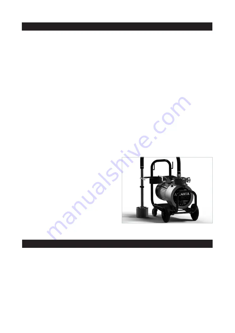
2) With the equipment, pressurized hose and gun, turn the 

pressure regulator (nº 5, Fig. 1) for the equipment to the 

minimum setting (anticlockwise).

3) Remove the spray gun safety catch. Holding a metallic 

part of the spray gun to the side of a correctly-grounded 

bucket, press the trigger to drain the product (aim the jet 

toward the side of the bucket) until gauge (No 7 Fig.1) 

indicate "0". 
4) Set the gun safety catch.
5) Open the product return key (No 4 Fig.1).
6) Turn the pressure regulator (No. 5 fig.1) clockwise until 

the product FLOWS SMOOTHLY through the product return 

Hose (No. 3 fig.1)

-  19  -

Before each start-up and especially after cleaning or repai-

ring the unit, a check must be made that all its elements are 

securely tightened.
The first time you use your equipment there is no need to 

depressurise it, as it is already supplied in a totally depres-

surised state, though it will be necessary to do this each 

time any maintenance or repair work is carried out.
Should this safety measure not be observed, this may lead 

to malfunctions, personal injury and accidents, which may 

prove to be fatal. SAGOLA S.A. does not accept any 

responsibility for the consequences of any non-compliance 

with these safety regulations
Before starting up the equipment, proceed according to the 

points given below, in the order in which they are indicated 

(if all the specified steps are followed on shutting down the 

equipment, it will be in the status referred to below):
1.- Open the product decompression valve (nº4 fig.1), to 

drain the equipment.
2.- Set the pressure regulator (nº5, fig.1) to the minimum 

position (turn anticlockwise).
3.- Check the product circuit for loose connections.
4.- Remove the product cap from the gun.
5.- Empty the cleaning solvent present in the interior of the 

pump, by means of the drain tube (nº3 fig.1). To do this, set 

the motor start-up switch to ON. Turn the regulator (nº5  

fig.1) gently to the right. Within a few seconds solvent will 

begin to run from drain tube (nº3 fig.1).
Collect the solvent issuing from the drain tube in a contai-

ner.

As soon as no more solvent runs out, turn the pressure 

regulator to the minimum setting (anticlockwise) and 

disconnect the motor by means of the switch (to the setting

“off”).
6.- Insert the suction probe (nº2 fig. 1) into the paint tank. If 

the pump has a gravity tank, fill this tank (in accordance 

with the quantity required for use). Place the drain tube in 

the paint container or in the gravity tank (nº1 fig.1).
7.- Set the motor switch (nº8 fig.1) to the ON position. Turn 

the pressure regulator (nº5 fig.1) gently to the right. Within 

a few seconds product will run from the drain tube (nº3 

fig.1). 
Move the pressure regulator again, to the minimum setting. 

Close the drain tube stopcock (nº4 fig.1). 

8.- Aim the gun towards a properly-grounded container. 

Press the trigger on the gun, holding a metallic part of the 

gun (the hand protector, for instance) in contact with the 

metallic container. Start turning the pressure regulator 

once again (nº5 fig.1) gently to the right. Within a few 

seconds, product will flow from the head of the gun which 

is not fitted with a cap. Maintain the flow of product until this 

is even (no air) from the head. Turn pressure regulator (nº5 

Fig.1) to the minimum position. Release the gun trigger 

and place insurance.
9.- Install the spray cap.
10.- Adjust the spray width:
- Increase the pressure by means of the pressure regulator 

(nº5, fig.1) until the product flowing from the gun is fully 

atomised. To avoid spraying too great a quantity of 

product, which may lead to excessive mist and premature 

wear on the cap and other parts of the equipment, always 

use the lowest pressure setting possible to obtain the 

performance and thickness in microns given by the manu-

facturer of the product.
- Once the atomising pressure for the product has been 

determined, if a greater quantity of product is required, it is 

preferable to use a cap of greater diameter than to increa-

se the pressure during application.
- To set the shape of the spray width, set the spray gun 

safety catch, loosen the cap attachment bolt and turn to the 

desired direction. Tighten the cap attachment bolt.

Содержание 30940801

Страница 1: ...u a l d e i n s t r u c c i o n e s l i s t a d e r e p u e s t o s i n s t r u c t i o n m a n u a l s p a r e p a r t s l i s t m a n u a l d e i n s t r u e s d e s m o n t a g e m d e p e a s ATL...

Страница 2: ......

Страница 3: ...uesta en marcha p g 7 9 Despresurizaci n p g 7 10 Funcionamiento p g 8 11 Parada p g 8 11 1 Parada de corta duraci n p g 8 11 2 Parada con finalizaci n de trabajo p g 8 12 Limpieza p g 9 13 Mantenimie...

Страница 4: ...junto a un muy bajo nivel de contaminaci n Equipo compuesto de serie por Bomba modelo ATLANTA 500 ATLANTA 800 Manual de Instrucciones Envase Como elementos opcionales y complementarios del equipo Mang...

Страница 5: ...Tuber a de retorno del producto 4 Llave de retorno del producto 5 Regulador de Presi n 6 Salida de Producto 7 Man metro 8 Interruptor el ctrico 9 V vula antirretorno 10 V lvula 11 Tacos fabricados en...

Страница 6: ...ante de los productos que vaya a utilizar productos a aplicar diluyentes etc ya que pueden generar reacciones qu micas incendios y o explosiones o ser t xicos irritantes o nocivos y en todo caso pelig...

Страница 7: ...ubo de purga n 3 fig 1 Para ello accionar el interruptor de arranque del motor posici n de encendido Accionar el regulador n 5 fig 1 hacia la derecha suavemente En unos segundos empezara a salir disol...

Страница 8: ...l producto atomiza si necesita aplicar mayor cantidad de producto recomendamos que preferentemente utilice una boquilla de mayor paso antes que aumentar la presi n de aplicaci n 13 3 Para conseguir la...

Страница 9: ...terruptor el ctrico n 8 fig 1 3 Cuando salga el disolvente por la Tuber a de retorno de producto n 3 fig 1 cierre la llave de retorno n 4 fig 1 4 Accione suavemente el mando del regulador de presi n n...

Страница 10: ...1 39 57250804 4 40 81560016 1 41 85760075 1 42 87260407 1 43 87261813 1 44 82560001 1 45 86060010 1 46 80860004 1 47 80660314 1 48 80660413 1 49 86060012 1 50 86464002 1 51 80660308 5 52 80860402 4 5...

Страница 11: ...20 1 39 57250804 4 40 81560016 1 41 85760078 1 42 87260407 1 43 87260414 1 44 82560001 1 45 86060010 1 46 80860004 1 47 80660314 1 48 80660413 1 49 86060012 1 50 86464001 1 51 80660308 5 52 80860402 4...

Страница 12: ...para el usuario o las personas que se hallen pr ximas como consecuencia de escapes roturas etc El equipo est preparado para su uso a temperatura ambiente La temperatura m xima de servicio es de 50 C L...

Страница 13: ...est deteriorada La Pistola carece de Boquilla de Pulverizaci n El Filtro de producto de la Pistola est obturado La Boquilla de Pulverizaci n de la pistola est deteriorada El producto tiene viscosidad...

Страница 14: ...o Sale aceite por la pistola o purga El motor se calienta en exceso El equipo toma excesiva presi n El Filtro de producto de la Pistola est obturado La Boquilla de Pulverizaci n de la pistola est atas...

Страница 15: ...s page 18 8 Start up page 19 9 Depressurisation page 19 10 Operation page 20 11 Stopping page 20 11 1 Short stop page 20 11 2 Stopping when work is finished page 20 12 Cleaning page 21 13 Maintenance...

Страница 16: ...d comply with all the indications described in this Manual This manual must be kept in a safe place accessible to all users of the unit The unit must be started and handled exclusively by personnel in...

Страница 17: ...on Probe 3 Product return hose 4 Product return key 5 Pressure Regulator 6 Product Outlet 7 Pressure Gauge 8 Electrical switch 9 Non return valve 10 Valve 11 Tacks manufactured in duralumin 12 Polyami...

Страница 18: ...es suited to the product to be transferred You must always connect the equipment and all the elements involved in the work process to a grounding connection to eliminate static electricity If its resi...

Страница 19: ...mp by means of the drain tube n 3 fig 1 To do this set the motor start up switch to ON Turn the regulator n 5 fig 1 gently to the right Within a few seconds solvent will begin to run from drain tube n...

Страница 20: ...o increase the pressure during application 13 3 To set the shape of the spray width set the spray gun safety catch loosen the cap attachment bolt and turn to the desired direction Tighten the cap atta...

Страница 21: ...rom the gun hoses and the rest of the unit with a cloth soaked in thinner Keep gasket areas free of accretions and foreign bodies The air cap is a precision component Any deformation especially in the...

Страница 22: ...0 1 39 57250804 4 40 81560016 1 41 85760075 1 42 87260407 1 43 87261813 1 44 82560001 1 45 86060010 1 46 80860004 1 47 80660314 1 48 80660413 1 49 86060012 1 50 86464002 1 51 80660308 5 52 80860402 4...

Страница 23: ...320 1 39 57250804 4 40 81560016 1 41 85760078 1 42 87260407 1 43 87260414 1 44 82560001 1 45 86060010 1 46 80860004 1 47 80660314 1 48 80660413 1 49 86060012 1 50 86464001 1 51 80660308 5 52 80860402...

Страница 24: ...erous situations for the user or personnel standing near the unit as a consequence of leaks breakages etc The equipment has been designed for use at ambient temperature The maximum operating temperatu...

Страница 25: ...ilter is clogged The cap is worn The paint is too thick The material is too thick Insufficient pumping pressure The gun filter is clogged The suction probe and or suction filter are loose dirty or dam...

Страница 26: ...tor Place the equipment in a location where the ventilator air intake is not impeded Replace the bearings or the motor Replace it Send the unit to the S A T SAGOLA In accordance with Directive 2006 42...

Страница 27: ...rranque p g 31 9 Despressuriza o p g 31 10 Funcionamento p g 32 11 Parada p g 32 11 1 Parada de curta dura o p g 32 11 2 Parada com finaliza o de trabalho p g 32 12 Limpeza p g 33 13 Manuten o p g 33...

Страница 28: ...amento leia atentamente tenha em conta e cumpra integralmente todas as indica es descritas neste manual Conserve o equipamento num lugar seguro e acess vel para todos os usu rios do mesmo O equipament...

Страница 29: ...bsor o 3 Tubula o de retorno do produto 4 Chave de retorno do produto 5 Regulador de press o 6 Sa da de produto 7 Man metro 8 Chave el trica 9 V lvula anti retorno 10 V lvula 11 Tacos de duralum nio 1...

Страница 30: ...cas Se for necess rio aplicar produtos especiais consulte a SAGOLA S A Leia e aplique com aten o todos os dados instru es e medidas de seguran a indicados pelo fabricante dos produtos que vai utilizar...

Страница 31: ...para ON Rode o regulador n 5 Fig 1 suavemente para a direita Dentro de poucos segundos solvente come ar a correr a partir do tubo de drenagem n 3 Fig 1 Recolhe se o solvente a partir de emiss o do tu...

Страница 32: ...o m ximo do produto recomenda se que de prefer ncia usar uma etapa principal do bocal em vez de aumentar a press o de aplica o 13 3 Para obter a forma desejada do ventilador operar a trava de seguran...

Страница 33: ...a de suc o n 2 fig 1 e introduza a tubula o de retorno do produto n 3 fig 1 2 Desligue o motor operando o interruptor de alimenta o No 8 Fig 1 3 Quando o solvente sair pela tubula o de retorno do prod...

Страница 34: ...360320 1 39 57250804 4 40 81560016 1 41 85760075 1 42 87260407 1 43 87261813 1 44 82560001 1 45 86060010 1 46 80860004 1 47 80660314 1 48 80660413 1 49 86060012 1 50 86464002 1 51 80660308 5 52 808604...

Страница 35: ...82360320 1 39 57250804 4 40 81560016 1 41 85760078 1 42 87260407 1 43 87260414 1 44 82560001 1 45 86060010 1 46 80860004 1 47 80660314 1 48 80660413 1 49 86060012 1 50 86464001 1 51 80660308 5 52 8086...

Страница 36: ...situa es de perigo para o usu rio ou para as pessoas que se encontrem nas imedia es em decorr ncia de escapamentos rupturas etc Aequipamento est preparado para ser usado temperatura ambiente A temper...

Страница 37: ...anificados A v lvula de suc o est danificada A pistola n o tem bocal de pulveriza o O filtro do producto da pistola est obturado O bocal de pulveriza o da pistola est danificado Aviscosidade do pintur...

Страница 38: ...do regulador Verifique a tens o de entrada para o motor Colocar el equipo en un lugar en el que no se impida la aspiraci n de aire por parte del ventidalor Mudan a de rolamentos ou motor Substituir En...

Страница 39: ......

Страница 40: ...CHER DIENST PROFESSIONNELLE REPARATURGARANTIE SERVI O DE ASSIST NCIA T CNICA GARANT A DE REPARA AO PROFISSIONAL SERVIZIO DI ASSISTENZA TECNICA GARANZIA DI RIPARAZIONE PROFESSIONALE Tel 34 945 214 150...

Отзывы: