SAFIRE 2400Di, 2600Di, 3200Di and 3600Di Diesel / fuel oil heaters
6
USAGE, INSTALLATION AND MAINTENANCE
January 2012
SF-LÄMMITIN OY Tilhenkatu 1 20610 Turku Finland Puh/Fax +358(0)2-2443282
6
MALFUNCTION
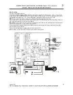
(To identify the LEDs: see wiring diagram)
NORMAL FUNCTION
Green LED
above the switch of the basic
control panel: the heater is on and gets
current.
Green LED (flame)
on the control panel and on the end
of the heater: the flame sensor has detected a flame in
the burner.
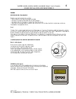
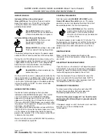
A blinking dot on the circuit board display: the pump is
operating.
MALFUNCTIONS
The
green LED
above the switch is not on when
starting the heater: the heater’s power supply is off.
If the LED is not on after the start process (about 6 1/2
min.) the heater goes into aftercooling mode and turns
off. This will happen f. ex. if the fuel system is empty
during the start. If you don’t notice anything unusual,
you may try to restart the heater.
The
green LED (flame)
turns off when the heater is
operating, the red LED on the end of the heater is on,
and the heater turns off: the fuel tank may be empty or
the fuel inlet is defective. Check the situation.
The
yellow LED
on the end of the
heater: The voltage is too low (less than
10,8 V or 9 V during the start). During the
start process the voltage can be lower.
Usually undervoltage during the start is caused by too
thin and/or too long power supply cables, oxidation in
some connection or otherwise bad contact. Check the
battery first, then the wires and connections. If the
yellow LED is on during operation and the heater turns
off, the battery is probably about to drain.
The
red LED
on the end of the heater:
the heater is turned off because of a
malfunction displayed on the circuit
board.
Usually this is caused by lack of fuel, which stops the
combustion; the error code on the circuit board display
is 3.
NB!
If you have turned off the heater after some
malfunction, you can see the latest error code on the
display again by turning the switch to the position
“VENT”: the number of the latest malfunction which
caused the heater to turn off shows on the display.
ERROR CODE NUMBERS ON THE CIRCUIT BOARD
DISPLAY
Number 1:
Overheating.
Overheating is usually caused by a blockage on the
normal warm air circulation (f. ex. too much restriction
on the warm air grilles or too much fuel. See p. 7,
Examination).
Number 2
: The flame sensor electrode is sooty or
defective. Clean the electrode (see p. 8). A short circuit
may have occurred on the housing.
Number 3:
The heater has turned off because the
combustion has stopped. Usually this is caused by lack
of fuel or a block in the fuel system.
Number 4:
The glow plug is defective, the connection
might be loose, or either the connector or the wire might
be defective.
Number 5:
The flame fan or its wires are defective.
Number 6:
The main fan or its wires are defective.
Number 7:
Undervoltage (see p. 5, Indicator LEDs).
Number 8:
The pump’s electric circuit is broken.
Number 9:
The temperature sensor of the circulating
air or its wires are defective.
Letter A
means that the heater wasn’t turned off
normally. This is caused by either a rapid voltage drop
or because the power supply is cut off with the main
switch before the aftercooling process is finished. Turn
the switch to VENT position for a little while, the heater
will start normally.
The dot on the circuit board display is supposed to blink
same freguency as pump. If this does not happen and
the pump does not make a tapping noise, and there isn’t
any malfunction, the pump doesn’t get current. The
problem is either on the pumps wires, in the spool or on
the circuit board.
If the dot on the display blinks but the pump does not
make a tapping noise and the wires are ok, the problem
is in the pump usually because of clouded fuel.
+ -


