SAFIRE 2400Di, 2600, 3200Di and 3600Di Diesel / fuel oil heaters
9
USAGE, INSTALLATION AND MAINTENANCE
December 2007
SF-LÄMMITIN OY Tilhenkatu 1 20610 Turku Finland Puh/Fax 358(0)2-2443282
CHECKING AND CLEANING THE PUMP
Check the pump by letting an air bubble into the hose. On one pulse the fuel pushes forward about 18–20
mm. If the fuel advances slowly, there might be a blockage. Air bubbles indicate an air leak on the suction or
in the pump.
If the pump doesn’t operate properly although the dot on the error code display blinks, or if you verify by
measuring that the pump’s performance is not sufficient although the pulse frequency is right and there aren’t
any blockages, the problem might be in the pump. The most common malfunctions in the pump are:
1. Blockage in the pump, or restriction or jamming of the piston caused by external impurities or
clouded fuel.
2. Corrosion caused by water during a long period of time.
3. Leakage of the check valve during the suction caused by impurities or corrosion.
CLEANING MINOR IMPURITIES AND CLOUDED FUEL IN THE PUMP
1. Release the hose connectors from the pump.
2. Now you can press isopropanol (a common anti-freeze for gasoline engines and truck air brakes)
through the pump.
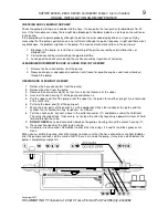
OPENING AND CLEANING THE PUMP
1. Release the hose connectors from the pump.
2. Release the wires from the pump.
3. Remove the connector strip (8) so that it rests on the filaments of the spool.
4. Unscrew the iron housing (1) of the pump and remove it.
5. Pull the upper end (3) of the pump out of the spool (4), the piston (9) and the spring (10) are removed
at the same time.
6. Pull also the lower end (5) of the pump out.
7. Wash the inner parts of the pump f. ex. with isopropanol. Check the function of the piston and the
cylinder: there shouldn’t be any “roughness” or stiffness.
8. Test the check valve: connect a hose in the outlet connector (11) and blow air under the fluid level.
The valve should not leak. If necessary, try to clean the valve by squeezing a powerful stream of fluid
forward through the valve.
9.
DO NOT OPEN
the sealed connection between the pump’s housing (6) and the valve’s housing (7):
the connection specifies the right piston stroke.
10. Assemble in reverse order. Remember to check that the o-rings (12 and 13) and their grooves are
clean.
When you assemble the pump, check the clamps to make sure that the hose connections are tight. Bubbles
after the pump reveal leaks on the suction. NB! If there is air inside the pump, it may take a while before the
pump is completely empty of air.


