


© Safe Fleet | May 2018 | All rights reserved | Part #: 700-1111 R2
Title of Document
p. 24
Performing AVM Calibration
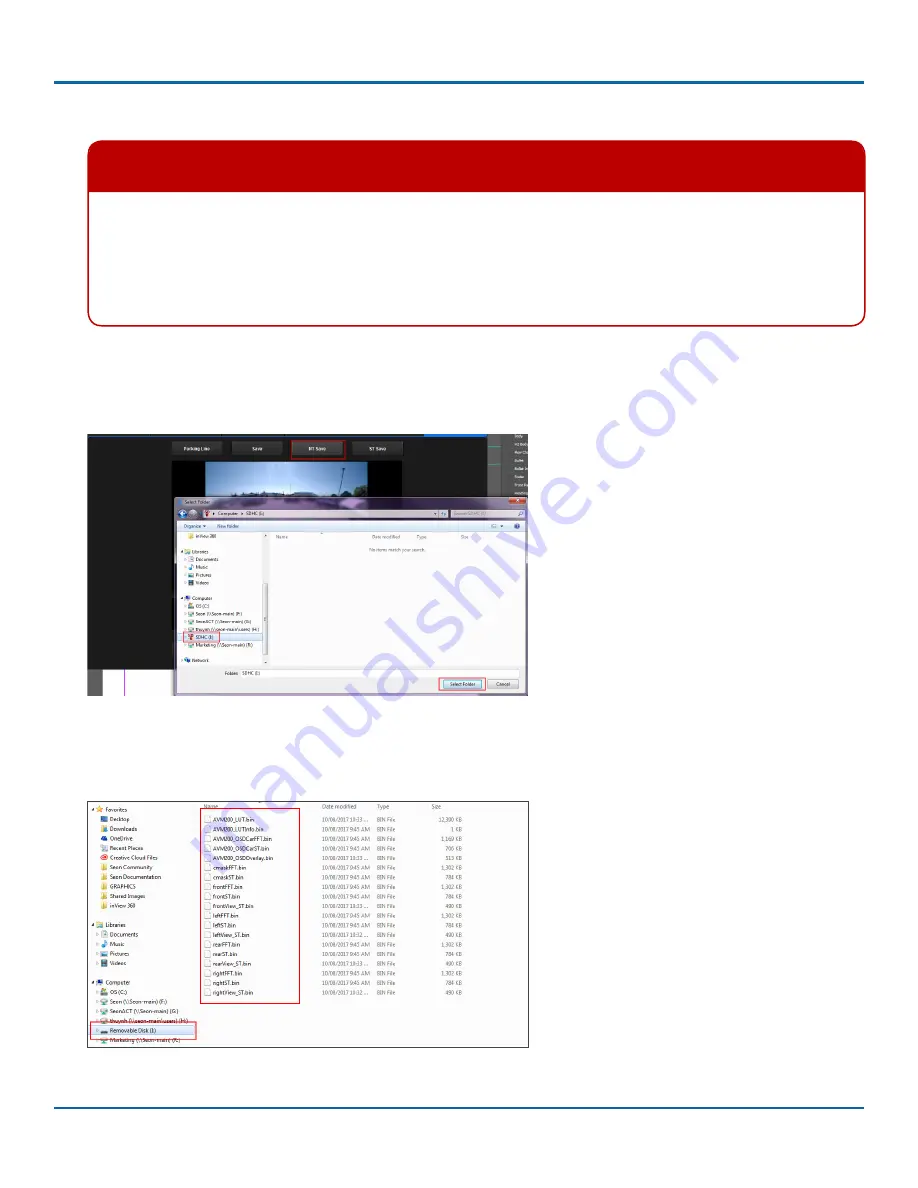
5. Click
NT Save
or
ST Save
Warning: Do not save in both modes
Do NOT click both NT Save and ST Save buttons. You can only save one set of calibration files on to the SD card.
If you choose to save in both modes, the files may interfere with one another, and the ECU may not be able to
load the images properly.
If you saved in both modes on the SD card, delete all contents on the card and save again before transferring
back to the ECU.
6.
Navigate to your SD card folder in Windows Explorer. Ensure that the SD card is empty by deleting the 4 camera files
that were there previously (if you haven’t already done so).
7. Click
Select Folder
to copy the calibration files to the SD card.
8.
Navigate to the SD card folder with Windows Explorer and verify that the calibration files were copied to the card. You
should see files similar to the ones in the following image. If no files appear on the card, attempt to save again or
contact Seon for help.
9. Remove SD card and transfer it back to the ECU in the vehicle.


