ENGLISH
3.
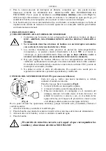
Connect the delivery pipe or hose directly to the pump mouth. If the pump is used in fixed
installations it is advisable to connect it to the pipe with a coupling so as to facilitate
disassembly and reinstallation. If a hose is used, fit a threaded hosetail on the pump mouth.
Wrap the thread with suitable material to ensure an effective seal (teflon tape or similar).
4.
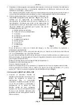
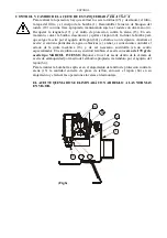
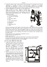
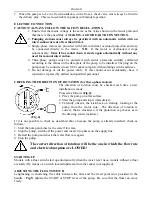
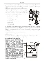
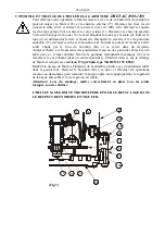
For fixed installations we advise the use of the lifting device
DSD2 (available on request -
Fig.2
) to facilitate pump
maintenance operations. When fitted between the pump
delivery aperture and the pipe, it avoids having to remove the
delivery pipe during maintenance jobs. The DSD2 device is
composed of 8 parts:
A.
Pipe anchoring bracket
B.
3/4" pipes (not supplied)
C.
Slide
D.
Pipe guide columns
E.
Foot
F.
Screw TCEI M10X25
G.
Base bracket
H.
Nut M10
I.
Pump flange screw
L.
Pump
(Fig.2)
The foot is positioned on the bottom of the tank and fixed with expansion screws of suitable
dimensions. The pipe guide bracket must be positioned at the top of well or borehole and
inserted in the end of two 3/4” pipes (not supplied), which act as a slide. The two pipes connect
the bracket to the foot. Position the base bracket in contact with the pump suction strainer near
the delivery aperture, secure everything to the strainer cover with the screws provaided to lock
the strainer cover.
Remove the top screw from the flange on the delivery side ( I ).
Assemble the anti-rotation bracket ( G ).
Replace the screw ( I ).
Extract the slide from the coupling foot and connect it to the delivery port of the pump.
Using the screw F and the nut H, fix the slide to the pump as indicated in the figure.
Reposition the slide/pump assembly on the foot (
Fig.2
).
INSTALLATION
DRENAG 1000-1200
1.
Connect the delivery pipe or hose directly to
the pump mouth. If the pump is used in fixed
installations it is advisable to connect it to the
pipe with a coupling so as to facilitate
disassembly and reinstallation. If a hose is
used, fit a threaded hosetail on the pump
mouth. Wrap the thread with suitable material
to ensure an effective seal (teflon tape or
similar).
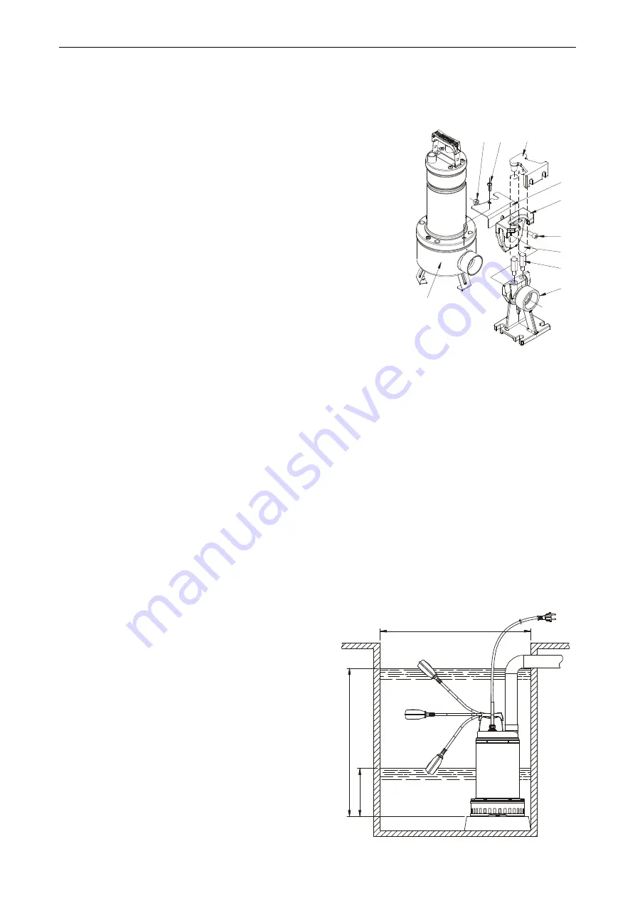
2.
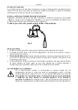
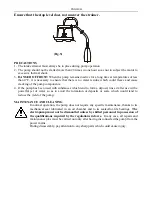
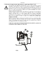
On the version provided with a float switch,
ensure that the float can move freely (SEE THE
PARAGRAPH ON ADJUSTING THE FLOAT
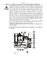
SWITCH). Ensure that the
minimum
dimensions
of the borehole are as in
Fig.3
.
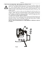
The dimensions of the borehole must also be
calculated with relation to the quantity of water
arriving and to the pump flow rate so as not to
subject the motor to excessive starting
operations.
(Fig.3)
H
I
A
G
C
F
B
D
E
L
600x600
O
N
OF
F
Содержание DRENAG 1000-1200
Страница 89: ...59 5 2 5 3 99 6 6 1 IEC 364 6 2 CEI 64 2 6 3 7 7 1 99 100 101 30 20 GRINDER 1400 M 7 2 7 3 2 7 4...
Страница 95: ...65 2 A B C D B C D 3 A B B 4 A B C A B C 5 A B C A B C...
Страница 114: ...84 5 5 1 5 2 5 3 99 6 6 1 IEC 364 6 2 CEI 64 2 6 3 7 7 1 99 100 101 30 20 GRINDER 1400 M 7 2 7 3 2 7 4...
Страница 120: ...90 4 A B C A B C A A B C A B C...
Страница 133: ...103 GRINDER...


