background image

4-10

                                         2nd Ed: May 31, 2002

SYS FIFTY FIVE X POH

4.2.3

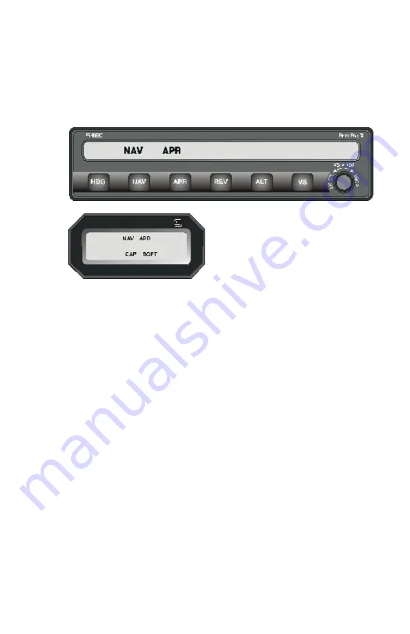
Approach (APR) Mode Switch

The APR Mode provides increased sensitivity for VOR or GPS approaches.
The pilot may also select this mode if increased sensitivity is desired for
enroute NAV tracking. To engage this mode press the APR switch on the
Programmer / Computer. NAV and APR will be displayed on the
annunciator.

If the aircraft is equipped with a
remote annunciator NAVAPR, CAP,
and SOFT will be displayed.

4.2.4

GPS Steering (GPSS) Mode

NOTE:

The Autopilot is equipped with a GPS Steering (GPSS)
Mode that can be used for normal GPS course tracking
or for GPS approach. In GPSS Mode, the heading bug
and / or course arrow position has no effect on the
autopilot and may be preset for the missed approach
heading, etc..., as desired.

NOTE:

When operating in the GPSS Mode and properly coupled
to the GPS receiver, the autopilot will automatically steer
the aircraft around the GPS approach without further
heading or course inputs required by the pilot.

NOTE:

The autopilot will track only those segments of the
approach contained in the GPS Navigator database.
Procedure turns and holding patterns are not usually
contained in the data base.

Содержание System 55X

Страница 1: ...System Fifty Five X Autopilot Pilot s Operating Handbook ...

Страница 2: ...tes pages changed added or deleted by revision Record of Revisions Retain this record in front of handbook Upon receipt of a revision insert changes and complete table below Edition Number Publication Date Insertion Date Initials 1 st Edition November 8 2000 2 nd Edition May 31 2002 ...

Страница 3: ...2 Normal Operating Procedures 4 7 4 2 1 Heading Mode 4 7 4 2 2 NAV Intercept and Tracking 4 7 4 2 2 1 Pilot Selectable Intercept Angles DG or HSI 4 9 4 2 3 Approach APR Mode Switch 4 10 4 2 4 GPS Steering GPSS Mode 4 10 4 2 5 GPSS Operating Procedures 4 11 4 2 5 1 Pilot Selectable Intercept Angles GPSS Mode 4 11 4 2 6 Standard GPS Approach 4 12 4 2 7 GPS Steering GPSS Approach 4 13 4 2 8 Reverse R...

Страница 4: ... Selectable Intercept Angles Optional HSI 4 27 4 3 7 Glide slope Intercept Tracking 4 27 4 3 8 Manual Arm Automatic Capture 4 30 4 3 9 Procedure Turn Localizer Back Course Approach Optional HSI 4 31 4 3 10 Localizer Back Course Intercept and Tracking Optional HSI 4 34 4 4 System Failure and Caution Annunciations 4 37 4 5 Autopilot Disconnect 4 38 4 6 Yaw Damper If Installed 4 38 4 6 1 Yaw Damper C...

Страница 5: ...d DG 4 20 4 3 4 1 Procedure Turn Localizer Approach Tracking Opt HSI 4 24 4 3 5 1 Straight In Localizer Approach Tracking Opt HSI 4 26 4 3 7 1 Glide slope Intercept Track 4 28 4 3 7 2 Procedure Turn for Glide slope Approach 4 29 4 3 9 1 Back Course Procedure Turn HSI 4 33 4 3 9 2 Back Course Straight In Approach Opt HSI 4 36 ...

Страница 6: ...2nd Ed May 31 2002 1 1 SYS FIFTY FIVE X POH SECTION 1 INTRODUCTION ...

Страница 7: ...pilot while in flight NOTICE The information in this manual must be used in conjuction with the FAA approved Airplane Flight Manual Supplement AFMS Pilot Operating Handbook Supplement POHS or Supplemental Flight Manual SFM Refer to the specific AFMS POHS or SFM for your aircraft s specific information and emergency operating procedures If the autopilot is to be used during Instrument Flight Rules ...

Страница 8: ...1st Ed May 31 2002 2 1 SYS FIFTY FIVE X POH SECTION 2 BLOCK DIAGRAM ...

Страница 9: ...E C R I N C R HDG NAV APR REV TRIM ALT GS VS R D Y C W S F A I L G P S S VS x 100 F F X IFTY IV E TRIM ON FAIL T RI M T RI M T RI M T RI M A P DISC TRIM INTR PT CW S YAW DAMPER OPTIONAL YAW SERVO OPTIONAL A P MASTER SWITCH TURN COORDINATOR AUTOPILOT DISCONNECT TRIM INTERRUPT SW ITCH CONTROL WHEEL STEERING SWITCH TRIM MONITOR SWITCH TRIM COMMAND SWITCH NOT AVAILABLE ON ALL AIRCRAFT FLIGHT DIRECTOR ...

Страница 10: ...2nd Ed May 31 2002 3 1 SYS FIFTY FIVE X POH SECTION 3 AUTOPILOT OVERVIEW ...

Страница 11: ...switch the computer acknowledges the mode causing the appropriate annunciator to illuminate The Roll Computer receives select input signals from the Directional Gyro DG or Horizontal Situation Indicator HSI Very High Frequency Omni directional Radio VOR Localizer LOC or Global Positioning System GPS Deviation Indicators and the Turn Coordinator It then computes roll servo commands for stabilizatio...

Страница 12: ...2nd Ed May 31 2002 4 1 SYS FIFTY FIVE X POH SECTION 4 PROCEDURES ...

Страница 13: ...5 seconds during test Satisfactory completion of the SELF TEST is indicated when the Ready RDY annunciator remains on at the end of the 5 second self test Should a fault be detected the FAIL annunciator will remain on at the conclusion of the self test and the autopilot will not operate NOTE If the autopilot detects the Turn Coordinator rotor speed as low or not turning the display will remain bla...

Страница 14: ...owly out pilot may have to assist a heavy yoke 7 VS Knob ROTATE CCW Pitch control should move slowly in 8 A P DISC Trim Interrupt Switch on control yoke PRESS Verify the autopilot disconnects 9 HDG Mode ENGAGE 10 DG or HSI HDG bug MOVE LT RT Roll control should follow the HDG bug 11 Altitude Hold ALT button PUSH Slowly pull out nose up on the pitch control Autotrim should run nose down with TRIM f...

Страница 15: ... control should follow the left right needle movement 13 REV Modebutton PUSH Roll control should respond opposite to the course arrow and CDI left right needle inputs 14 Autopilot Master Switch If FD Equipped SELECT FD Note the roll pitch and trim servos are disengaged The steering bar should be in view on the attitude indicator 15 HDGMode ENGAGE MOVE HDG bug 45 degrees left The roll steering bar ...

Страница 16: ...aged NOTE If the aircraft is equipped with Optional Yaw Damper reference the Yaw Damper Section of this POH for the Pre flight check NOTE If either the Manual Electric Trim or Auto trim fails any portion of the Pre flight Test move the Trim Master Switch to OFF DO NOT USE THE ELECTRIC TRIM UNTIL THE FAULT IS CORRECTED With the Trim Master switch OFF the Autopilot Trim Indicators and Audio Warning ...

Страница 17: ...th left right deviation and course information With an HSI the heading bug is not used during tracking To intercept and track a VOR or GPS course select the desired course with the HSI Course Pointer and engage the NAV Mode If your aircraft is equipped with a DG the HDG bug must be set to the desired course before engaging NAV Mode The HDG bug provides course information when using the NAV Modes I...

Страница 18: ...d SOFT Approximately 60 seconds later the turn rate maximum is reduced to 15 standard rate and the lowest level of sensitivity is acheived SOFT At this point the optional remote annunciator will indicate NAV and SOFT The CAP annunciator will extinguish If the course pointer on an HSI or HDG bug on a DG is within 5 of center and needle deflection is less than 10 the computer will immediately establ...

Страница 19: ... may select an angle of intercept less than the standard 45 Simply place the heading bug to the desired heading to be used for the course intercept and push both HDG and NAV switches simultaneously Both HDG and NAV will be annunciated The selected heading will now be flown until the autopilot computes that an on course turn must be made to minimize overshoot at the point of intercept At the time t...

Страница 20: ...OTE The Autopilot is equipped with a GPS Steering GPSS Mode that can be used for normal GPS course tracking or for GPS approach In GPSS Mode the heading bug and or course arrow position has no effect on the autopilot and may be preset for the missed approach heading etc as desired NOTE When operating in the GPSS Mode and properly coupled to the GPS receiver the autopilot will automatically steer t...

Страница 21: ... be annunciated 4 To delete the GPSS function push the NAV button again or select HDG or CWS Mode NOTE Turns while in GPSS Mode can exceed the standard rate by 20 to 30 4 2 5 1 Pilot Selectable Intercept Angles GPSS Mode The autopilot may also be programmed for Pilot Selectable Intercept Angles while using the GPSS Mode Simply push and hold the HDG button then push the NAV button twice HDG NAV and...

Страница 22: ...PSS Mode anytime the NAV button is pressed twice The following CAUTION will apply to those systems CAUTION With the autopilot in the GPSS Mode NAV and GPSS will be annunciated In this mode guidance is received directly from the GPS Navigator regardless of what is displayed on the NAV indicators HSI CDI If the GPS Navigator has a valid flight plan active and the autopilot is in the GPSS Mode the au...

Страница 23: ...he aircraft begins a turn toward the Initial Approach Fix IAF or that segment of the approach that transitions to the selected approach 4 Monitor the autopilot as it moves around the approach using vertical speed and altitude hold to fly the vertical elements of the approach 5 Select HDG to accomplish a procedure turn 6 Engage the GPSS again to complete the approach 4 2 8 Reverse REV Mode The Reve...

Страница 24: ...shes while in the VS Mode this is an indication of excessive error between actual vertical speed compared to selected vertical speed usually in a climb and the pilot should adjust aircraft power or reduce the vertical speed command as appropriate 4 2 10 Altitude ALT The Altitude Mode ALT may be engaged with any roll mode displayed by pressing the ALT Mode switch The aircraft will maintain the pres...

Страница 25: ...ve the VS selector knob Example 6 equals 600 Feet Per Minute FPM rate of climb If desiring a specfic attitude press CWS switch Allow the aircraft to stabilize in the desired attitude for 2 to 3 seconds release the Control Wheel Steering switch and the autopilot roll and pitch servos will engage and synchronize with the aircraft s turn rate and vertical speed NOTE If the aircraft roll angle is grea...

Страница 26: ...s annunciated and the pilot disengages the autopilot there will be residual out of trim force at the control wheel Be alert if the autopilot is disengaged while TRIM is annunciated 4 2 13 Autotrim With the autotrim functioning normally the aircraft elevator trim will be maintained automatically when the Trim Master switch is on and a pitch mode is activated When the elevator trim is in motion TRIM...

Страница 27: ...ction of trim FWD for nose down or AFT for nose up TRIM will be annunciated and will flash while the trim is in motion NOTE The S TEC trim system is designed to accept any type of single failure mechanical or electrical without uncontrolled operation resulting To ensure that no hidden failures have occurred conduct a trim pre flight check prior to every flight ...

Страница 28: ...llows the intercept angle The point that this turn begins is variable depending on the aircraft position and closure rate to the course However the turn will always begin between 100 full scale needle deflection and 20 of full scale During the intercept sequence the system operates in maximum gain and sensitivity to needle position and motion and can command the aircraft at 90 of the standard rate...

Страница 29: ...he INBOUND procedure turn heading follow the localizer intercept and tracking procedures for standard DG noted below 4 3 3 1 Procedure Turn Localizer Approach and Tracking with Standard D G 1 a Tune navigation radio to LOC frequency b Set heading bug to published outbound LOC heading c Push REV Mode switch 2 a Set heading bug to outbound procedure turn heading b Press HDG Mode switch 3 a In 90 inc...

Страница 30: ...n between 100 full scale needle deflection and 20 of full scale During the intercept sequence the system operates in maximum gain and sensitivity to needle position and motion and can command the aircraft at 90 of the standard rate turn When the localizer course is intercepted and the needle is centered indicating course capture initiation of the tracking gain program is automatic If the aircraft ...

Страница 31: ...e from the station and aircraft speed Therefore angles greater than 45 are not recommended 4 3 4 Procedure Turn Localizer Approach Optional HSI Select the appropriate localizer frequency Set the course pointer to the INBOUND localizer course and engage the Reverse REV Mode to track the localizer front course outbound or back course inbound When a localizer is channeled and REV Mode is selected the...

Страница 32: ...level is maintained for about 15 seconds while wind correction angle is established Turn rate maximum is then reduced to 45 of standard rate The optional remote annunciator will indicate APR REV CAP and SOFT If the course selector is within 5 of center and needle deflection is less than 10 the computer will immediately establish this sensitivity level when REV is selected Set the heading bug to th...

Страница 33: ...o published outbound procedure turn heading b Press HDG Mode switch 3 a In 90 increments set heading bug to inbound procedure turn heading b When established on inbound procedure turn heading press NAV Mode switch 4 a Once established in NAV Mode set heading bug to the published missed approach heading If a missed approach is declared at the Middle Marker MM disconnect the autopilot and stabilize ...

Страница 34: ...ally shallows the intercept angle The point that this turn begins is variable depending on the aircraft position and closure rate to the course However the turn will always begin between 100 full scale needle deflection and 20 of full scale During the intercept sequence the system operates in maximum gain and sensitivity to needle position and motion and can command the aircraft at 90 of the stand...

Страница 35: ...ag is displayed When this occurs the FAIL anunciation will illuminate 4 3 5 1 Straight In Localizer Intercept and Tracking Optional HSI 1 a Tune navigation radio to LOC frequency b Set course pointer to published inbound LOC course heading c Press NAV Mode switch 2 a Once NAV Mode is established heading bug can be set to published missed approach heading b At the Middle Marker if a missed approach...

Страница 36: ...nd below To arm the automatic glide slope GS capture function the following conditions must be met a NAV receiver must be tuned to the appropriate frequency b Glide slope signal must be valid no flag c Autopilot must be in NAV APR ALT Modes d Aircraft must be 60 or more below GS centerline during the approach to the intercept point and within 50 needle deviation of the localizer centerline at the ...

Страница 37: ...At the Missed Approach Point MAP Decision Height DH or the autopilot s minimum operating altitude whichever is higher disengage the autopilot to execute a manual landing or a Go Around maneuver If a Missed Approach is declared the autopilot can be re engaged after a stabilized climb has been established NOTE If vectored to intercept the localizer too close to the glide slope intercept point result...

Страница 38: ... and GS annunciations will illuminate along with the ALT annunciation f Upon capture of the glide slope the ALT annunciation will extinguish Ref 4 3 7 Glide slope Intercept and Track 3 a If a circling or straight in approach to the ILS course is established descend to approach altitude well in advance of reaching the Outer Marker b Upon reaching approach altitude press the ALT Mode switch c Upon c...

Страница 39: ...lope centerline by 50 needle deflection the GS annunciator flashes a warning It also flashes when the GS flag is displayed When this occurs the FAIL annunciation will illuminate NOTE If it becomes necessary to establish a holding pattern at the Outer Marker automatic glide slope arming can be disabled by pressing the APR switch a second time while in the NAV APR Mode The GS annunciator will flash ...

Страница 40: ...s near 50 of full scale If on this inbound leg you wish to rearm the glide slope press the APR switch once 4 3 9 Procedure Turn Localizer Back Course Approach Optional HSI Select the appropriate localizer frequency Set the course selector to the INBOUND Localizer FRONT Course and engage the NAV Mode to track the localizer back course outbound or front course inbound When a localizer is channeled a...

Страница 41: ...ned for about 15 seconds while the wind correction angle is established Turn rate maximum is then reduced to 45 of standard rate The optional remote annunciator will indicate NAV APR CAP and SOFT If the course selector is within 5 of center and needle deflection is less than 10 the computer will immediately establish this sensitivity level when NAV is selected Set the heading bug to the outbound p...

Страница 42: ...the navigation receiver to LOC frequency b Set course pointer to published inbound LOC front course heading c Press NAV Mode switch The autopilot will capture and track back course outbound 2 a Set heading bug to the published outbound procedure turn heading b Press the HDG Mode switch 3 a In 90 increments set heading bug to the inbound procedure turn heading b Press REV Mode switch Autopilot will...

Страница 43: ...ure rate and gradually shallows the intercept angle The point at which this turn begins is variable depending on the aircraft position and closure rate to the course However the turn will always begin between 100 full scale needle deflection and 20 of full scale During the intercept sequence the system operates in maximum gain and sensitivity to needle position and motion and can command the aircr...

Страница 44: ... also flashes when the HSI NAV flag is displayed When this occurs the FAIL annunciator will illuminate 4 3 11 Pilot Selectable Intercept Angles Optional HSI The pilot may select an angle of intercept less than the standard 45 This is done by placing the heading bug on the desired heading to be used for the course intercept while simultaneously pushing the HDG and REV switches HDG APR and REV is an...

Страница 45: ... to missed approach heading after course capture NOTE To establish a selected angle of intercept dual mode intercept on the back course set the course pointer to the published inbound front course heading and the heading bug to the desired heading to establish the selected angle intercept Press the HDG and REV Mode switches simultaneously Upon capture of the back course the autopilot automatically...

Страница 46: ...50 needle Cross check raw deviation or more NAV data compass HDG radiooperation FlashingNAV Indicates invalid Check NAV Radio REV orAPR Radio Navigational for proper reception SteadyFAIL Signal Use HDG Mode until problem is corrected Flashing VS Indicates excessive Reduce VS command Vertical Speed Error and or adjust power over selected VS as appropriate usually climb Flashing GS Indicates Off Che...

Страница 47: ...Press the Autopilot Disconnect Trim Interrupt switch on the aircraft s control wheel 3 Pull the aircraft s AUTOPILOT Circuit Breaker 4 If the pitch axis of the autopilot is engaged activate the Trim Command switch on the aircraft control wheel FWD or AFT 4 6 Yaw Damper Optional Configuration may vary with installation 4 6 1 Yaw Damper Controls The Yaw Damper Master switch is a three position cente...

Страница 48: ... freedom of controls 4 Yaw Damper must be OFF for takeoff and landing 4 6 3 Yaw Damper In flight Procedures 1 Trim the aircraft for the phase of flight being conducted climb cruise descent with the rudder trim 2 Adjust the Yaw Damper Trim Control to center 3 With the Yaw Damper Master switch in the AUTO position engage the Autopilot and note that Yaw Damper engages 4 Make small Yaw Damper Trim adj...

Страница 49: ... the programmed modes Accurate flight director operation requires alertness by the pilot and monitoring of the movement of the display Keeping it matched is quite simple However control inputs must be timely for accurate flight director following of the desired command 4 7 Single Cue Flight Director Operation Optional This system which integrates both the roll axis and pitch axis offers synchroniz...

Страница 50: ...he flight director place the FD AP master switch in the FD position This disables the autopilot servos allowing the pilot to control the aircraft to the flight director commands To engage the autopilot without interruption simply place the FD AP master switch in the FD AP position ...

Страница 51: ...2nd Ed May 31 2002 5 1 SYS FIFTY FIVE X POH SECTION 5 SPECIFICATIONS ...

Страница 52: ...ge Turn Coordinator Power required 14 28 VDC Flag voltage detector operating limits 9 0 VDC approx Flag RPM detector operating limits Nominal RPM less 20 Current Requirements 0 8 Amp max Weight 1 8 lbs Dimensions 3 28 X 3 28 X 5 62 in Roll Servo Power required 14 28 VDC Current requirements Included in system current requirements Weight 2 9 lbs Dimensions 3 75 X 3 75 X 7 25 in Pitch Servo Power re...

Страница 53: ...red 0 2 Amp max Weight 0 75 lbs Dimensions 1 60 X 3 42 X 3 80 in Trim Servo OPTIONAL Power required 14 28 VDC Current requirements 0 5 Amp avg 2 0 Amp max Weight 2 9 lbs Dimensions 3 75 X 3 75 X 7 25 in Yaw Damper OPTIONAL Power required 14 28 VDC Current requirements 1 5 Amp max continuous Weight 0 9 lbs Dimensions 4 5 X 1 75 X 5 25 in System Current Requirements Approximate 14 VDC 28 VDC Average...

Страница 54: ...2nd Ed May 31 2002 6 1 SYS FIFTY FIVE X POH SECTION 6 GLOSSARY ...

Страница 55: ...te GPS Global Positioning System GPSS Global Positioning System Steering GS Glideslope HDG Heading HSI Horizontal Situation Indicator IFR Instument Flight Rules LOC Localizer N A Not Applicable NAV Navigation POH Pilot Operating Handbook POHS Pilot Operating Handbook Supplement PSI Pounds Per Square Inch RDY Ready REV Reverse RPM Revolutions Per Minute SFM Supplemental Flight Manual TSO Technical ...

Страница 56: ... Telephone 940 325 9406 FAX 940 325 3904 1 800 USA STEC www s tec com Information in this document is subject to change without notice 2002 S TECCorporation Allrightsreserved PrintedintheUnitedStatesofAmerica S TEC and the S TEC logo are registered trademarks of S TEC Corporation P N 87109 Date May 31 2002 Printed in USA ...

Отзывы: