13
INSTALLATION—CONTROL PANEL AND ELECTRICAL CONNECTIONS
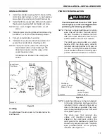
The fused disconnect must be in the OFF
position and the fuses removed before
wiring of the control box begins.
2.
Run wires from the encoder and motor to the control
box using approved conduit.
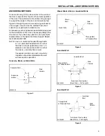
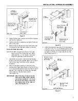
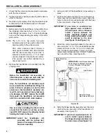
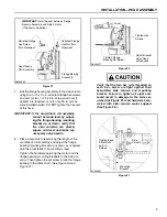
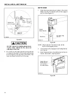
Coil Cord Installation
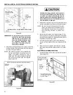
DO NOT twist the cord during installation.
Twisting the coil cord will cause it to tangle
or fail, leading to serious problems.
Ensure that the coil cord does not have
any excessive slack when installation is
complete. It should not touch the floor.
1.
Manually open the door. Allow the cord to hang
down to remove any twists in the cord.
2.
Route the coil cord to a junction box near the side
column and through the hole in the junction box.
3.
Place cord grip nut over the end of the coil cord. The
nut was shipped in the small parts carton.
4.
Tighten the nut to attach the cord grip to the junction
box.
CONTROL PANEL AND ELECTRICAL
CONNECTIONS
Once the door has been assembled, see the Rytec Sys-
tem 3 Drive & Control Installation & Owner’s Manual for
information on control panel installation, electrical con-
nections, door limit settings, and initial door start-up pro-
cedure.
NOTE: If a floor loop is used, all wiring from the
fused disconnect to the control box and
from the control box to the motor mount
side column, as well as conduit running
from the control box to the floor, is pro-
vided by the door owner/installer or the
electrician. All wiring and conduit must
meet all local and state codes. Wires pro-
vided with the door are labeled with termi-
nal or contact numbers.
OPEN AND CLOSE DOOR LIMIT POSITIONS
See the Rytec System 3 Drive & Control Installation &
Owner’s Manual for the proper procedure for setting the
open and close door limits. The open and close limit
door positions are detailed below.
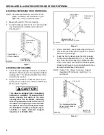
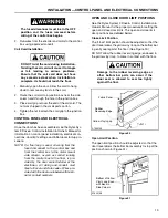
Close Limit Position
The “close” limit position should be adjusted so that the
door travel allows the yellow vinyl loop on the bottom bar
to gently seal against the floor. (See Figure 30.)
DO NOT allow the rubber reversing edge, enclosed in
the yellow vinyl loop, to come in contact with the floor.
Damage to the rubber reversing edge or
other bottom bar parts can occur if the
door seal is allowed to seal too tightly
against the floor.
Figure 30
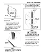
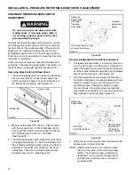
Open Limit Position
The open limit position should be adjusted so that the
door travel allows the bottom bar assembly to stop at the
position shown in (Figure 31.)
Figure 31
Yellow Vinyl Loop
Fabric Panel
Rubber
¹₂
–1 i
Reversing Edge
A7500195
A7500196
Bottom of Yellow
Vinyl Loop Even
with Bend in
Side Column
Содержание Pharma-Roll
Страница 1: ...Pharma Roll Installation Manual Revision January 15 2009 0715009 Rytec Corporation 2007...
Страница 2: ......
Страница 23: ...NOTES 19...
Страница 24: ......

