

16
INSTALLATION—PHOTO EYE INSPECTION
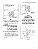
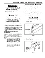
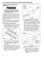
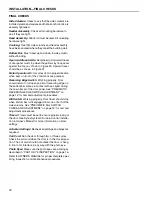
Kill Switch Sensitivity Adjustment
The kill switch assembly is a normally closed contact.
The PVC hose is on the upper air input post.
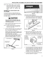
1.
Remove the wires from the contact terminals and
attach an ohmmeter across the two terminals.
(See Figure 39.)
2.
To adjust the switch, turn the small adjusting screw,
located on the face of the switch, clockwise or coun-
terclockwise until continuity is achieved. Then turn
the screw two turns clockwise for final adjustment.
Ohmmeter should continue to show continuity.
Turning the screw clockwise decreases sensitivity.
Turning the screw counterclockwise increases sen-
sitivity. (See Figure 39.)
Figure 39
3.
Reconnect the wires onto the switch. Replace the
access cover on bottom bar.
NOTE: If the kill switch is set too sensitive, it may
cause the door to stop during the opening
or closing cycles. If this occurs, readjust
the kill switch sensitivity setting.
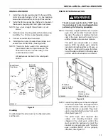
PHOTO EYE INSPECTION
NOTE: The door has two sets of safety photo eyes
used as a safety device to prevent the door
from closing if an object is in the path of the
door panel. The photo eyes are not meant
to be used as door activators. Both sets of
eyes must be working correctly for the door
to operate.
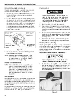
Indicator Lights
With power applied to the control panel, the green light
on each photo eye indicates the eye is powered up.
When the yellow light on the receiver module is also lit,
the emitter and receiver module, from the same set, are
properly aligned.
Placing your hand in front of the receiver breaks the light
path and causes the yellow light to go out. Removing
your hand causes the yellow light to go back on.
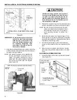
Photo Eye Test
Personnel and objects should not be in the
path of the door when the following
inspection is performed. If the photo eyes
are not working properly, the door could
strike the personnel or object in its path.
1.
Raise the door to the fully open position.
2.
Place an object in the path of the front photo eye
beam. Then attempt to close the door by pressing
the button on the control panel. The door should not
operate.
3.
Remove the object and cycle the door to verify that
the front set of eyes is working properly. If the eyes
are not working properly, see “Photo Eye Trouble-
shooting” below.
4.
Repeat the above steps on the rear set of photo
eyes to verify that both sets are working properly.
Photo Eye Troubleshooting
If either green light is not lit, make sure power is turned
on, and that all wiring has continuity and is installed and
connected properly. If the green lights are on, but the
yellow light is off, check the alignment of the emitter and
receiver modules.
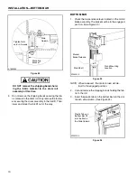
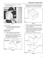
RESETTING BOTTOM BAR ASSEMBLY
Turn off power to the door. Make sure
power is locked off and properly tagged.
1.
Position the breakaway tabs on one end of the bot-
tom bar assembly in the side column channel. Lift
the other end of the bottom bar and position the
breakaway tabs in the remaining side column chan-
nel. (See Figure 40.)
Figure 40
A7500202
PVC Hose Must
Be Tight on Air
Kill Switch (On
Sensitivity
Adjustment Screw
Same Side as
Door Motor)
Remove Wires
to Test and
Adjust Switch
Input Post
A7500038
Содержание Pharma-Roll
Страница 1: ...Pharma Roll Installation Manual Revision January 15 2009 0715009 Rytec Corporation 2007...
Страница 2: ......
Страница 23: ...NOTES 19...
Страница 24: ......