Rydeen BSS-ONE Скачать руководство пользователя страница 15


13


If you have


other


questions


about


the


BSS-ONE

,


please


contact


your


retailer or

Te chnical Support:


Te lephone:


1-877-777-8811


(within


USA only)


or 1-310-787-7880


Email:

[email protected]

Web Address:

www.rydeenmobile.com

Technical Support Contact Info

8. One Year Limited Warranty

RYDEEN MOBILE (a


manufacturer


of


"

RYDEEN

"


products)


warrants


product


(BSS-ONE)

only to the


original


purchaser


as


described


following:


Warranty


Period


Rydeen warrants


this product


for


a period


of


one


(1) year


from


the


original 

purchase date.


Warranty


Coverage


This warranty covers all defects in material and workmanship except as specified 
below.

1. Any products distributed outside of the USA by Rydeen North America, Inc. 

(Rydeen) or which is


not purchased in the USA or Canada unless the product is 

purchased through the USA Military Exchange Service.


2. Any product(s) which are purchased from an unauthorized retailer (in store or 

online).


3. Any products in which the serial number label or the model number label are 

removed, torn, modified or replicated.


4. Any damage defects or malfunctions resulting from any of following:


a)


When defect occurs during shipment of product (freight 
carrier's responsibility).


b) Installation or removal of product.


c) Accidents, act of nature, misuse, abuse, neglect, unauthorized product 

modification or failure to follow product owner's manual instructions.

d) Any repair or attempt to repair without RYDEEN authorization.
e) Any other cause which is not related to product defect.
f) Any cosmetic damages due to normal wear and tear.
g) Any consumable items (such as fuse or batteries).

If any problems develop with your Rydeen products during or after the Limited

7. Technical Support Contact Info


Содержание BSS-ONE

Страница 1: ...Owner s Manual BSS ONE Single Sensor Blind Spot Detection System V1 0 ...

Страница 2: ......

Страница 3: ...allation 6 Installation Diagram 7 5 Function Introduction 10 BLIND SPOT DETECTION BSD 10 LANE CHANGE ALERT LCA 11 SYSTEM FUNCTION 12 6 Specifications 12 7 Technical Support Contact Info 13 8 One Year Limited Warranty 13 9 To Obtain Warranty Service 14 10 FCC ISED Compliance Statement 14 11 Copyright 15 12 Disclaimer 16 13 Troubleshooting 16 ...

Страница 4: ...ment in a safe place for future reference If you have any further questions about your BSS ONE operation feel free to call RYDEEN Toll Free at 1 877 777 8811 within USA only for product support or visit our website www rydeenmobile com The BSS ONE IS NOT TO replace any functions drivers shall ordinarily perform in driving a motor vehicle nor does it decrease the need for drivers to stay vigilant a...

Страница 5: ...ke rising out of the unit unusual odor emanating from the unit STOP USING THE UNIT IMMEDIATELY Contact the nearest RYDEEN retailer or call RYDEEN Customer Service for assistance Toll Free 1 877 777 8811 within USA only DO NOT mount your BSS ONE on any non automotive form of transportation motorcycles bikes ATV s watercraft The appearance of the product shown in this manual may be different from th...

Страница 6: ...ct please make sure that all product accessories are complete What s in the Box Radar Sensor Holder Main Cable Sensor Extension Cable Left Indicator Right Indicator Buzzer Splice Connector K 520 Primer Adhesion Promoter Allen Key large Allen Key small Drill Bit Φ14mm ...

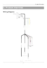
Страница 7: ...Product Overview 5 3 Product Overview Wiring Diagram ...

Страница 8: ...h cable clamps or electrical tape Do not allow any bare wiring to remain exposed Make sure that the cables and wires will not interfere with or become caught in any of the vehicle s moving parts especially brake doors or any of the vehicle s controls If the wiring of this unit is located under a front seat make sure it does not obstruct seat movement Route all leads and cords carefully around the ...

Страница 9: ...tion Failure to properly install and connect the system components may cause damage to the product and operation of the system 3 The radar sensor should be kept in a position with low interference otherwise it may cause the detection to be insensitive or not work properly 4 The radar sensor should be kept clean The adhesion of ice snow or mud will affect the normal operation of the sensor Installa...

Страница 10: ...r sensor from the centerline of the vehicle and along this axis locate a position parallel to the ground 15 5 inches to 31 inches from the ground so that the sensor is mounted inside the bumper Mark this spot on the outside of the bumper with painter s tape Pillar A ACC IGN GND Indicator L Indicator R Buzzer ...

Страница 11: ...IMER MUST BE USED Step 4 Connect the radar sensor to the harness Route the harness assembly from the rear exterior of the vehicle into the cabin utilizing a grommet Secure the harness away from any heat sources and moving parts Pass the harness through the grommet ensuring the harness and connector do not become damaged Route the harness to the desired location and affix it to the vehicle using cab...

Страница 12: ...dicator Lamps 1 The left indicator will illuminate when a vehicle is in your left blind spot while driving This indicator will flash and an audible tone will sound when your left turn signal is activated while there is a vehicle in the left blind spot 2 The right indicator will illuminate when a vehicle is in your right blind spot while driving This indicator will flash and an audible tone will soun...

Страница 13: ... car When a vehicle is approaching from behind the LED on the side of the oncoming car will light up to warn the driver When the turn signal is activated and the driver prepares to change lanes if there is an oncoming car behind the warning light on the side of the oncoming car will continue to flash and give an audible warning Level II Level Warning Way Detection Zone Target Conditions Level I LED...

Страница 14: ...ic Parameters Operational Temperature 40 85 Storage Temperature 40 85 Operation Speed 13 mph 20 km h Installation Angle 8 degrees 3 System Function BSD LCA Standard ISO 16750 Radiation Regulation FCC ISED Alarm Level Level I LED On Constant Level II LED Flash Buzzer On Hardware Parameters Input Voltage Range 12V 9V 16V Power supply IGN Terminal 12V Current Consumption 500mA 12V 6W max Buzzer Alarm...

Страница 15: ...r Canada unless the product is purchased through the USA Military Exchange Service 2 Any product s which are purchased from an unauthorized retailer in store or online 3 Any products in which the serial number label or the model number label are removed torn modified or replicated 4 Any damage defects or malfunctions resulting from any of following a When defect occurs during shipment of product fr...

Страница 16: ...ranty service requests from outside of the U S A even if product was purchased in the USA 3 Please include a copy of your original purchase receipt including Rydeen product model number purchase date retailer name address and a RA Number whenever your product is sent for warranty service 4 Rydeen will pay for all labor and material expenses for covered product during warranty period 5 Shipping add...

Страница 17: ...interference including interference that may cause undesired operation of the device L émetteur exempt de licence contenu dans le présent appareil est conforme aux CNR d Innovation Sciences et Développement économique Canada applicables aux appareils radio exempts de licence L exploitation est autorisée aux deux conditions suivantes 1 L appareil ne doit pas produire de brouillage 2 L appareil doit...

Страница 18: ... when Rydeen confirms that it is a quality problem Rydeen is not responsible for other losses and injuries please kindly note 13 Troubleshooting NO Issues Reasons Solutions 1 The system does not respond after starting the engine Incorrect connection or control unit failure Confirm that the IGN wiring fuse and controller are connected 2 The indicator does not light up Damaged indicator Replace the in...

Страница 19: ......

Страница 20: ...ll Rights Reserved RYDEEN is a registered trademark of Rydeen North America Inc These materials are protected by copyright law and international treaties Any unauthorized use reproduction or distribution of these materials or any portion herein will result in severe civil and criminal penalties and fines Violators will be prosecuted to the fullest extent of the law ...

Отзывы: