


36
REVT-05ERV
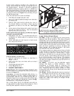
Spark Igniter
- A spark igniter is used to provide an
ignition spark for lighting the burners. The igniter is
mounted on the burner wrapper and is located above the
left-most burner as shown in
Figure 33
and can be easily
removed for service without removing any part of the
burners. During the ignition process, voltage is applied
to the Electrode, which arcs to Ground (
See Figure 34
)
creating a spark that ignites the left burner; which then
lights the adjacent burner and the flame travels from
burner to burner until all are lit.
The Spark Electrode is connected to the ignition control
by an 8 mm silicone-insulated, stranded, high voltage
wire. The wire uses a ¼" female quick-connect on the
electrode end and a female spark plug- type terminal on
the ignition control end.
NOTE: In order to maximize spark energy to the
Electrode, the high voltage wire should not touch
the cabinet unnecessarily.
Also, for proper operation, the Electrode to Ground gap
(spark gap) must be set correctly at 0.125 ± 0.015 inch
(3.2 ± 0.4 mm).
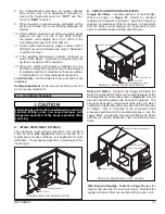
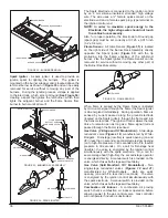
Flame Sensor
- A Flame Sensor (
Figure 35
) is located
on the right side of the Burner Rack Assembly directly
opposite the Spark Igniter (
Figure 33
) with the tip
protruding into the flame envelope of the right-most
burner. Like the Spark Igniter, the Flame Sensor can be
removed for service without removing any other part of
the Burner Rack Assembly.
FIGURE 34 - SPARK IGNITER
FIGURE 35 - FLAME SENSOR
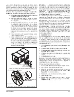
FIGURE 33 - BURNER RACK ASSEMBLY
FIGURE 32 - BURNER REMOVAL
When flame is sensed by the Flame Sensor (indicated
by micro-amp signal through the flame) the Spark Igniter
is de-energized immediately. During operation, flame is
sensed by current passed along the ground electrode
(located on the Spark Igniter), through the flame and into
the Sensor electrode. The Ignition Control allows the Gas
Valve to remain open as long as a flame signal (current
passed through the flame) is sensed.
Gas Valve (2-Stage and 5:1 Modulation)
- A two-stage
redundant valve (
Figures 18
) manufactured by White-
Rodgers. First-stage (low-fire) is quick opening (on and
off in less than 3 seconds), second-stage is slow opening
(on to high-fire pressure in 40 seconds and off to low-fire
pressure in 30 seconds). On a call for first-stage heat
(low-fire), the valve is energized by the ignition control
simultaneously with the spark electrode. On a call for
second-stage heat (high-fire), the second-stage operator
is energized directly. A manual switch is provided on the
valve, which closes both stages without delay.
Gas Valve (Split Manifold, 10:1 Modulation)
– Two
single-stage redundant valves (
Figures 18 and 21
)
manufactured by White-Rodgers. Both are quick
opening (on and off in less than 3 seconds). The valve
is energized by the ignition control simultaneously with
the spark electrode. A manual switch is provided on the
valve, which closes both stages without delay.
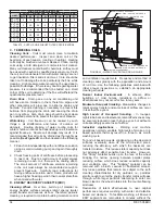
Combustion Air Inducer
- A combustion air proving
switch checks combustion air inducer operation before
allowing power to the gas control valve. Gas controller
will not operate if inducer is obstructed.
ELECTRODE
ELECTRODE
SPARK IGNITER
BURNER WRAPPER
INSHOT BURNERS
GAS REGULATOR VALVE
0.125±0.015
ROLLOUT SWITCH
FLAME SENSOR
ROLLOUT SWITCH
ORIFICES
MANIFOLD
GROUND
SPARK IGNITOR
BURNER RACK ASSEMBLY
INSHOT BURNER
BURNER SCREWS
BURNER SUPPORT
Содержание ENERVENT+ EVT-09 Series
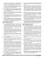
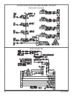
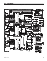
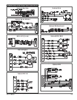
Страница 30: ...30 REVT 05ERV UNIT WIRING DIAGRAM ...
Страница 31: ...REVT 05ERV 31 UNIT WIRING DIAGRAM CONTINUED ...
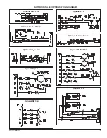
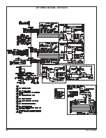
Страница 47: ...REVT 05ERV 47 UNIT WIRING DIAGRAM XVIII WIRING DIAGRAMS ...
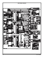
Страница 48: ...48 REVT 05ERV UNIT WIRING DIAGRAM CONTINUED ...
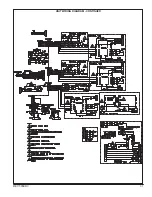
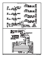
Страница 50: ...50 REVT 05ERV Optional Heat Cool Inputs Optional Pre Post Heat ...
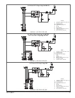
Страница 57: ...REVT 05ERV 57 DIAGRAM 15 5 1 MODULATION GAS POST HEAT DIAGRAM 14 2 STAGE GAS POST HEAT ...