


16 REVT-05ERV
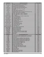
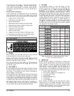
TABLE 3 - MINIMUM CFM WITH ELECTRIC POST-HEAT OPTION
C. ELECTRIC POST-HEAT
Post-Heat will stage on and cycle with thermostat
demand. Number of stages will vary depending on Post-
Heat assembly. See Post-heat wiring diagram on unit
for sequence of operation. Limit controls are factory-
set and are not adjustable. A minimum air volume must
be maintained through Post-Heat section per
Table 3
to
avoid tripping the limit during long periods of operation.
D. GAS POST-HEAT
Construction
- Heat exchanger is tubular construction.
Standard material is aluminized steel for all units except
the EVT-10 and EVT-12 where stainless steel is required.
Stainless steel is optional for all other units unless the
air temperature supplied to the heat exchanger is below
45°F, where it is required. Burners are inshot, aluminized
steel, with direct spark ignition and the gas valve is a
redundant automatic dual stage with manual shut-off.
Controls
- Ignition Control provides positive, direct
ignition of burners on each operating cycle. The system
permits main gas valve to stay open only when burners
are proven to be lit. Should flame loss occur, the gas
valve closes, shutting off the gas supply to the burners.
Ignition module has coded LED to indicate status and
aid in troubleshooting. Redundant limit controls are
factory installed with fixed temperature setting. Heat limit
controls protect heat exchanger and other components
from overheating. Flame roll-out switch, flame sensor and
combustion air proving switch protect system operation.
Available Selections
-
See Chart 4 on Page 46
for
available capacities and specifications by unit size.
Chart
5 on Page 46
lists performance data for all gas heat units.
E. MOTORIZED DAMPERS
Intake Air
- Damper mounts behind the outdoor air intake
hood. Opens when the ERV is energized and closes
when de-energized. Powered by B30 damper motor.
ELECTRIC POST-HEAT - REQUIRED MINIMUM AIR FLOW
UNIT
NON CFM MAX KW
NO
STAGES KW AVAIL MIN CFM
EVT-09
1,000
9.6
1
9.6
800
EVT-19
1,900
19.2
2
1
19.2
9.6
1,600
800
EVT-28
2,800
19.2
1
19.2
1,600
EVT-36
3,600
19.2
2
1
38.4
19.2
3,200
1,600
EVT-46
4,600
38.4
2
1
38.4
19.2
3,200
1,600
EVT-62
6,200
57.6
3
2
1
57.6
38.4
19.2
4,800
3,200
1,600
EVT-74
7,400
60
2
1
60
30
5,000
2,500
EVT-88
8,800
90
3
2
1
90
60
30
7,500
5,000
2,500
EVT-10
10,000
90
3
2
1
90
60
30
7,500
5,000
2,500
EVT-12
12,000
120
4
3
2
1
120
90
60
30
10,000
7,500
5,000
2,500
Exhaust Air
- Mounts between the exhaust blower and
the return air exhaust hood. Operates in conjunction with
Motorized Intake Air Damper. Powered by B31 damper
motor.
F. DIRTY FILTER SENSOR
Measures pressure drop across Intake and Exhaust
Filters and sends a signal to field wired alarm when filters
require maintenance.
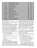
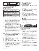
G. FROST CONTROL
Extremely cold outdoor air temperatures can cause
moisture condensation and frosting on the energy
recovery wheel (ERW). The temperature below which
frost will begin to accumulate is referred to as the Frost
Threshold Temperature, and is a function of both outside
temperature and indoor relative humidity (
See Table 4
).
Frost formation causes reduction of airflow through the
ERW; therefore, without frost control, energy recovery
and airflow may be significantly reduced.
Frost control is an optional feature that will control wheel
frosting. Three frost Control options are available:
1. Exhaust Only
2. Variable ERW Speed
3. Electric Pre-Heat
FROST THRESHOLD TEMPERATURE (OD DB)
INDOOR
RH (%)
INDOOR DB TEMPERATURE
70
o
F
72
o
F
75
o
F
80
o
F
20
-14
-13
-11
-8
30
-3
-2
-1
3
40
5
7
9
11
50
13
13
15
18
60
18
19
21
26
Exhaust Only
- An exhaust temperature sensor value
will signal the controls to shutdown the supply blower
when the temperature in the exhaust quadrant reaches
a field adjustable temperature (Factory set 18°F). This
temperature can only be reached when the wheel is
frosted over. Normal operation resumes after a heat rise
of 16°F. To avoid depressurization of the conditioned
space, automatic or pressure operated fresh air dampers
may be required as part of the ventilation system.
Modulating Wheel Frost Control
- The modulating
wheel feature uses a variable frequency drive to modulate
the wheel’s speed based on outside air temperature. The
wheels RPM will slow as the temperature drops, hence
lowering the effectiveness of the wheel and preventing
icing up. The variable frequency drive is programmed to
have minimum frequency of 15hz so the wheel speed does
not interfere with the wheel rotation sensor’s operation.
Values in
Table 5
have been derived from the accepted
empirical model to allow entering supply air to remove all
water deposited on the wheel by the exhaust. This option
is best used for applications where the hours required for
frost control are limited.
Electric Pre-Heat
- This is the recommended method
of preventing frost formation while ensuring required
ventilation rates for most cold climate applications. A
constant air temperature, above the frost threshold, is
TABLE 4 - FROST THRESHOLD GUIDELINES
Содержание ENERVENT+ EVT-09 Series
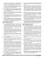
Страница 30: ...30 REVT 05ERV UNIT WIRING DIAGRAM ...
Страница 31: ...REVT 05ERV 31 UNIT WIRING DIAGRAM CONTINUED ...
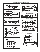
Страница 47: ...REVT 05ERV 47 UNIT WIRING DIAGRAM XVIII WIRING DIAGRAMS ...
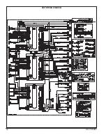
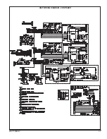
Страница 48: ...48 REVT 05ERV UNIT WIRING DIAGRAM CONTINUED ...
Страница 50: ...50 REVT 05ERV Optional Heat Cool Inputs Optional Pre Post Heat ...
Страница 57: ...REVT 05ERV 57 DIAGRAM 15 5 1 MODULATION GAS POST HEAT DIAGRAM 14 2 STAGE GAS POST HEAT ...