


REVT-05ERV 3
These instructions are intended as a general guide and
do not supersede local codes in any way. Authorities
having jurisdiction should be consulted before installation.
This Manual covers Full Featured Energy Recovery
Ventilators, this series offers 10 distinct unit capacities in
5 different cabinet sizes. These units offer a full line of pre-
heat and tempering options designed to deliver neutral
air (outside air equal to or below the temperature of the
exhaust air) to the ventilated space, as well as additional
options designed to deliver an additional heating or
cooling load,
See Page 15
for a full list and description
of options.
Communication and control of this unit can be achieved
through a bacnet compatible building automation system
like Metasys, or if ordered the unit can be controlled via
thermostat.
SUPPLEMENTAL POST-HEAT
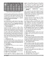
FIGURE 1 - TYPICAL CABINET FEATURES AND OPTIONS
II - GENERAL
III - PARTS ARRANGEMENT
Figure 1
shows the parts arrangement for the typical
cabinet, including major standard features and factory-
installed options that are offered and, therefore, may
be included in the unit being installed. The units shown
are typical of the entire series with regard to component
location, features, and options available
AIRFLOW CHOICE
BLOWER MOTOR
VIBRATION ISOLATORS
CONTROLS
MODULAR FRAME
EXHAUST AIR HOOD
OUTDOOR
AIR HOOD
DOUBLE-WALL CONSTRUCTION
DAMPER
AIR FILTERS
DEFROST CONTROLS
ACCESS DOOR
TEMPERING COILS
ENERGY RECOVERY CASSETTE
SILENT-PRO BLOWERS
BASE RAIL
WARNING
Improper installation, adjustment, alteration,
service or maintenance can cause property damage,
personal injury or loss of life. Installation and
service must be performed by a qualified installer,
service agency or the gas supplier.
WARNING
Cancer - www.P65Warnings.ca.gov
Содержание ENERVENT+ EVT-09 Series
Страница 30: ...30 REVT 05ERV UNIT WIRING DIAGRAM ...
Страница 31: ...REVT 05ERV 31 UNIT WIRING DIAGRAM CONTINUED ...
Страница 47: ...REVT 05ERV 47 UNIT WIRING DIAGRAM XVIII WIRING DIAGRAMS ...
Страница 48: ...48 REVT 05ERV UNIT WIRING DIAGRAM CONTINUED ...
Страница 50: ...50 REVT 05ERV Optional Heat Cool Inputs Optional Pre Post Heat ...
Страница 57: ...REVT 05ERV 57 DIAGRAM 15 5 1 MODULATION GAS POST HEAT DIAGRAM 14 2 STAGE GAS POST HEAT ...