Rupes BA31ES Скачать руководство пользователя страница 11

BEFORE STARTING THE TOOL

Before starting-up the tool, ensure that:
-  the packaging is complete and does not show signs of having been damaged

during storage or transport;

- the tool is complete; check that the number and type of components comply

with that reported in this instruction booklet;

-  the power supply and socket outlet can support the load reported in the table

and that indicated on the tool identification plate reproduced;

- the power supply cable and plug are in perfect condition;
- the ON/OFF switch (2) works properly though with the power supply

disconnected;

- the wheel spindle locking button (4) is released (rotate the abrasive wheel by

hand for at least one revolution);

- all the parts of the tool have been assembled in the proper manner and that

there are no signs of damage;

- the ventilation slots (14) are not obstructed.
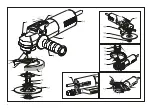
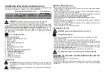
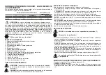
ASSEMBLING THE TOOL

DANGER:

never work without protective earmuffs (7)

Wear protective gloves!

- screw in the auxiliary handle (6); the handle can be mounted on the left or

right of the tool body;

- mount the dust brush (8) securely on the protective shield (7) (pushfit);
- mount the protective shield (7) with collar on the body of the tool using the

screws (10). Ensure that the protrusions on the collar (9) are inserted in the slots
cut into the flange of the adjustable protective shield (7);

- after tightening the screws (10) and collar (9), the adjustable protective shield

(7) must be able to rotate with a slight resistance approximately 20° in order
that it may be positioned as desired;

- connect the extraction device by the suction pipe in the nozzle (15).

The protective shield (7) must be mounted around the handle.

ASSEMBLY OF THE DISC HOLDER SANDING PAD AND THE

ABRASIVE DISC

1.Insert the disc pad (12) on the spindle (5);
2.fit the abrasive disc;
3.screw on the ring nut (11) and tighten it using the pin wrench (13) preventing

the spindle from moving with the 17 mmspanner or with the spindle locking
button (4).

11

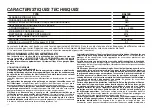
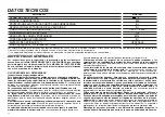
Sound pressure level / Sound power level            3 axis vibration level

(Surface grinding)

)

LPA

LWA          Uncertainty 

ah              Uncertainty 

dB(A)

m/s

2

BA 31ES

90

101

3

5,50

1,50

INFORMATOIN NOISE / MEAN ACCELERATION VALUE

The tools are suppressed in accordance for the prevention and elimination of radio
disturbances measured in accordance with standard: 

EN 60745

DANGER

The indicate measurements refer to new power tools.

Daily usa causes the noise and vibration values to change.
Displayed emission values are comparative and are to be employed for

a provisional assessment of the operator’s risk exposure during the work period.
Appropriate evaluation of work period must also include tool’s idle and stop
periods. These emission values represent the tool’s main applications. 
If the tool is used for other applications, with other accessories, or if it does not
undergo regular maintenance, emission values can significantly increase
during operations.

Use hearing protection!
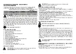
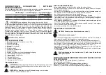
PARTS OF THE TOOL

1 - Technical data identification label
2 - ON/OFF switch
3 - Speed control
4 - Wheel spindle locking button
5 - Spindle
6 - Side handle
7 - Adjustable protective shield
8 - Dust brush
9 - Collar with protective shield fixing points
10 - Protective shield fixing screws
11 - Disc pad tapered ring nut
12 - Abrasive disc mouting plate
13 - Spanners
14 - Motor ventilation slots
15 - 29 mm Ø suction port

STARTING UP

WARNING

Pay attention to the mains voltage! The mains voltage must

correspond to the voltage indicated on the technical data identification
label (1).

DANGER 

Before any intervention on the electrical tool take the plug 

out from the socket

Содержание BA31ES

Страница 1: ...stofafzuiging ISTRUZIONI ORIGINALI PER L USO 3 TRANSLATION OF ORIGINAL OPERATING INSTRUCTIONS 8 CONVERSION DES INSTRUCTIONS DE FONCTIONNEMENT ORIGINAL 13 BERSETZUNG DES URSPR NGLICHEN BEDIENUNGSANLEIT...

Страница 2: ...2...

Страница 3: ...09 Marcatura di conformit Marchio di conformit EurAsian Marchio di Qualit Italiano Marchio C Tick Smaltimento dell apparecchio dismesso Freccia Agire in direzione indicata dal senso della freccia Alcu...

Страница 4: ...ale possono rompersi ed essere proiettati in aria Il diametro esterno e lo spessore del vostro accessorio devono essere adatti alle caratteristiche di capacit della protezione di sicurezza del vostro...

Страница 5: ...ndare in blocco la mola da taglio n applicare una pressione eccessiva Non tentare di rendere il taglio eccessivamente profondo Una forte pressione sulla mola aumenta il carico e la probabilit di torsi...

Страница 6: ...torello portadisco 12 sull albero portamola 5 2 inserire il disco abrasivo 3 avvitare la ghiera 11 e serrare con la chiave a pioli 13 mantenendo fermo l albero con la chiave da 17 mm o col pulsante di...

Страница 7: ...va fatta in funzione delle caratteristiche dei dischi di carta abrasiva e del materiale da lavorare ACCESSORI Dischi fibrati da 115 mm L utilizzo di utensili con diametro superiore porta ad un sovrac...

Страница 8: ...llow you to operate the tool better and safer SIMBOLS Warning symbol Warning message ISO7010 W001 Read instruction manual ISO7010 M002 Wear eye protection ISO7010 M004 Wear ear protection ISO7010 M003...

Страница 9: ...The configuration of the cutting grinding wheels or any other accessory mustperfectly adapt to the tool spindle Accessories with holes that cannot be aligned with the fitting components on the tools w...

Страница 10: ...PERATIONS Do not stall the cutting wheel or apply an excessive pressure Do not attempt to increase the cutting depth The application of a high pressure on the cutting wheel increases the load and the...

Страница 11: ...G PAD AND THE ABRASIVE DISC 1 Insert the disc pad 12 on the spindle 5 2 fit the abrasive disc 3 screw on the ring nut 11 and tighten it using the pin wrench 13 preventing the spindle from moving with...

Страница 12: ...he use of tools of larger diameter will overload the motor and drive system leading to rapid deterioration MAINTENANCE All maintenance operations are carried out with the power supply disconnected At...

Страница 13: ...r et plus s r SYMBOLES Symbole d avertissement Message d avertissement ISO7010 W001 Lisez le manuel d instruction ISO7010 M002 Porter des lunettes de protection ISO7010 M004 Porter une protection de l...

Страница 14: ...outil ne garantit pas un fonctionnement en toute s curit La vitesse nominale de l accessoire doit tre au moins gale la vitesse maximale indiqu e sur l outil Les accessoires fonctionnant une vitesse s...

Страница 15: ...z de coincer la meule tron onner ou d appliquer une pression excessive N essayez pas d effectuer de d coupes trop profondes Une forte pression sur la meule augmente la charge et donc les risques de to...

Страница 16: ...sur l outil lectrique extraire la fiche de r seau de la prise AVANT LA MISE EN SERVICE Avant de mettre la machine en service s assurer que l emballage est int gre et qu il ne montre aucun signe d end...

Страница 17: ...es abrasifs de 115 mm 17 L utilisation d outils ayant un diam tre sup rieur cause une su recharg du moteur et des organes de transmission qui provoque une d t rioration rapide ENTRETIEN outes les op r...

Страница 18: ...eine Maske ISO7010 M016 Schutzhandschuhe ISO7010 M009 Pr fzeichen EurAsian Qualit tskennzeichen Italienischem Qualit tskennzeichen C Tick Zeichen Entsorgung von au er Dienst Pfeil Act in der durch den...

Страница 19: ...er Nennspannung von 230V 50Hz basiert Im Falle von Spannungen und Frequenzen von verschiedenen Leistungswerten kann variieren Beziehen sich auf die technischen Spezifikationen Label auf die Nennwerte...

Страница 20: ...eibe nicht blockieren lassen noch berm igen Druck aus ben Nicht versuchen den Schnitt berm ig tief auszuf hren Ein starker Druck auf der Schleifscheibe erh ht die Last und die Wahrscheinlichkeit von V...

Страница 21: ...tiert sein 7 da sie den Bereich am Handgriff sch tzt MONTAGE DER SCHEIBENTR GER SCHLEIFTELLERS UND DER SCHLEIFSCHEIBE 1 Den Schleifteller 12 auf die Spindel 5 aufsetzen 2 Schleifscheibe aufschieben 3...

Страница 22: ...erkzeugen mit gr erem Durchmesser f hrt zur berlastung von Motor und AntriebKomponenten und damit zum Verschlei des Ger tes innerhalb k rzester Zeit PFLEGE DES GER TES S mtliche Eingriffe bei gezogene...

Страница 23: ...guantes de protecci n ISO7010 M009 Marca de conformidad La herramienta se incluye en la lista de EurAsian Marca de Calidad Italiana Marca C Tick Eliminaci n de fuera de servicio Flecha Ley en la dire...

Страница 24: ...o no aconsejados por el productor El hecho de que el accesorio se pueda fijar en la herramienta no garantiza un funcionamiento totalmente seguro La velocidad nominal del accesorio debe ser al menos ig...

Страница 25: ...IDAD ADICIONALES PARA LAS OPERACIONES DE CORTE ABRASIVO No bloquear la muela de corte ni aplicar una presi n excesiva No intentar que el corte resulte excesivamente profundo Una fuerte presi n sobre l...

Страница 26: ...re dB A m s 2 BA31ES 90 101 3 5 50 1 50 ANTES DE LA PUESTA EN SERVICIO Antes de poner en funcionamiento la m quina verificar que el embalaje est integro y no tenga se ales de da os debidos al transpor...

Страница 27: ...de 115 mm 27 La utilizaci n de herramientas con di metro superior provoca una sobre carga del motor y de los rganos de trasmisi n llev dolos a deteriorarse en un tiempo muy breve MANTENIMIENTO Todas l...

Страница 28: ...masker ISO7010 M016 Draag beschermende handschoenen ISO7010 M009 Merkteken van overeenstemming De tool is opgenomen in de lijst EurAsian Italiaanse Keurmerk C Tick Keurmerk Verwijdering van ontmanteld...

Страница 29: ...ast garandeert geen veilige werking De nominale snelheid van het accessoire moet minstens gelijk zijn aan de maximale snelheid die op het gereedschap is aangegeven Accessoires die met een hogere snelh...

Страница 30: ...EL Laat de snijschijf niet vastlopen en oefen ook niet een te grote druk uit Probeer niet om te diep door te slijpen Door harde druk op de slijpschijf wordt de belasting vergroot en bestaat de kans da...

Страница 31: ...RSCHIJF 1 Plaats de ondersteuningspad vulcofixpad 2 Monteer de fiberschijf 3 Draai vervolgens de moer op de spindel vast met de hand met behulp van de moersleutel 13 Hierbij dient de spindel vastgezet...

Страница 32: ...ORDEN 115 mm fiber schuurschijven Het gebruik van gereedschap met een grotere diameter leidt tot overbelasting van de motor en de transmissieorganen en dit heeft binnen zeer korte tijd slijtage ervan...

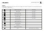
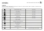
Страница 33: ...33 33 ISO7010 W001 ISO7010 M002 ISO7010 M004 ISO7010 M003 ISO7010 M016 ISO7010 M009 EurAsian C Tick...

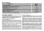
Страница 34: ...34 230 50 EPTA 01 2003 BA31ES II 900 1 500 4 000 115 M 14 2 1...

Страница 35: ...35...

Страница 36: ...EN 60745 1 2 3 4 5 6 7 8 9 10 11 12 13 14 15 29 1 LPA LWA ah dB A m s 2 BA31ES 90 101 3 5 50 1 50 36 2 4 14 7 6 y 8 7 10 9 10 9 7 20 15 7 1 12 5 2 3 11 13 17 4...

Страница 37: ...zo 20080 VERMEZZO CON ZELO Mi Italy Vermezzo con Zelo Mi 22 05 2016 2006 42 EU 2014 35 EU 2014 30 EU 2011 65 EU EN 60745 1 2009 A11 2010 EN 60745 2 3 2011 A2 2013 A11 2014 A12 2014 A13 2015 EN 55014 1...

Страница 38: ......

Страница 39: ......

Страница 40: ...rconi 3A Loc Vermezzo 20080 VERMEZZO CON ZELO Mi Italy Tel 02 946941 Fax 02 94941040 Uff Vendite e assistenza clienti Tel 02 94694312 e mail info_rupes rupes it web http www rupes com COD ART 9 2503 R...

Отзывы: