

171
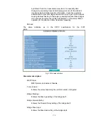
Instance Priority:
Spanning tree priority value for a specific tree instance(CIST or MSTI)
Bridge Mac Address:
The Mac Address of the bridge itself.
CIST ROOT PRIORITY:
Spanning tree priority value of the CIST root bridge
CIST ROOT MAC:
Mac Address of the CIST root bridge
CIST EXTERNAL ROOT PATH COST:
Root path cost value from the point of view of the bridge’s MST region.
CIST ROOT PORT ID:
The port ID of the bridge’s root port. In MSTP, peer port of a root port
may reside in defferent MST region or in the same MST region.The first
case indicates that the root port’s owner is the CIST regional root bridge.
CIST REGIONAL ROOT PRIORITY:
Spanning tree priority value of the CIST regional root bridge.Note that
CIST Regional Root bridge is different from CIST Root bridge.One
exception is that when a bridge belonging to an MST region happens to
be the root bridge of the CST(Common Spanning Tree). An MST Region
in the CST can be regarded as a common RSTP bridge.The IST(Internal
Spanning Tree) and MSTIs are transparent to bridges outside this region.
CIST REGIONAL ROOT MAC:
Mac Address of the CIST regional root bridge.
CIST INTERNAL ROOT PATH COST:
Root path cost value from the point of view of the bridges inside the IST.
CIST CURRENT MAX AGE:
Max Age of the CIST Root bridge.
CIST CURRENT FORWARD DELAY:
Forward Delay of the CIST Root bridge.
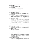
TIME SINCE LAST TOPOLOGY CHANGE(SECs):
Time Since Last Topology Change is the elapsed time in unit of seconds
for a bunch of “Topology Change and(or) Topology Change Notification
receiving” to occur. When new series of Topology Changes occur again,
this counter will be reset to 0.
TOPOLOGY CHANGE COUNT(SECs):
The per spanning tree instanceTopology Change Count expresses the
Содержание GS-2224L
Страница 1: ......
Страница 2: ......
Страница 34: ...24 Fig 2 15 Office Network Connection Fig 2 14 Peer to peer Network Connection ...
Страница 78: ...68 Fig 3 28 ...
Страница 83: ...73 Fig 3 31 ...
Страница 91: ...81 Fig 3 39 Fig 3 40 Fig 3 41 ...
Страница 103: ...93 Fig 3 54 Set up Typical Network Application Rules Finish Fig 3 55 Set up Typical Network Application Rules Finish ...
Страница 113: ...103 Fig 3 67 Ingress Port Fig 3 68 ...
Страница 115: ...105 Fig 3 71 Fig 3 72 Fig 3 73 ARP Fig 3 74 ARP ...
Страница 116: ...106 Fig 3 75 ARP Fig 3 76 ARP Fig 3 77 ARP Fig 3 78 ARP ...
Страница 117: ...107 Fig 3 79 ARP Fig 3 80 ARP Fig 3 81 ARP Fig 3 82 ARP ...
Страница 118: ...108 Fig 3 83 ARP Fig 3 84 ARP Fig 3 85 ARP Fig 3 86 ARP Fig 3 87 ARP ...
Страница 119: ...109 Fig 3 88 IPv4 Fig 3 89 IPv4 Fig 3 90 IPv4 ...
Страница 120: ...110 Fig 3 91 IPv4 Fig 3 92 IPv4 Fig 3 93 IPv4 Fig 3 94 IPv4 Fig 3 95 IPv4 ...
Страница 121: ...111 Fig 3 96 IPv4 Fig 3 97 IPv4 Fig 3 98 IPv4 Fig 3 99 IPv4 Fig 3 100 IPv4 ...
Страница 122: ...112 Fig 3 101 IPv4 Fig 3 102 IPv4 Fig 3 103 IPv4 Fig 3 104 IPv4 ...
Страница 123: ...113 Fig 3 105 IPv4 Fig 3 106 IPv4 Fig 3 107 IPv4 ...
Страница 124: ...114 Fig 3 108 IPv4 Fig 3 109 IPv4 Fig 3 110 IPv4 Fig 3 111 IPv4 ...
Страница 125: ...115 Fig 3 112 IPv4 Fig 3 113 IPv4 Fig 3 114 IPv4 ...
Страница 126: ...116 Fig 3 115 IPv4 Fig 3 116 IPv4 Fig 3 117 IPv4 ...
Страница 127: ...117 Fig 3 118 Action Fig 3 119 Rate Limiter ...
Страница 128: ...118 Fig 3 120 Port Copy Fig 3 121 DMAC Filter ...
Страница 129: ...119 Fig 3 122 VLAN ID Filter Fig 3 123 VLAN ID Filter Fig 3 124 Tag Priority ...
Страница 141: ...131 Fig 3 126 Set up Policy Rules Fig 3 127 Set up Policy Rules Fig 3 128 Set up Policy Rules ...
Страница 142: ...132 Fig 3 129 Set up Policy Rules Finish Fig 3 130 Set up Port Policies Fig 3 131 Set up Port Policies ...
Страница 143: ...133 Fig 3 132 Set up Port Policies Fig 3 133 Set up Port Policies Finish ...
Страница 144: ...134 Fig 3 134 Set up Typical Network Application Rules Fig 3 135 Set up Typical Network Application Rules ...
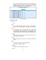
Страница 150: ...140 Delete Select one of entry from the table then click on Delete to delete this entry Fig 3 143 ...
Страница 159: ...149 Fig 3 145 ...
Страница 204: ...194 Fig 4 1 Fig 4 2 ...


