


18
2-1-4-2. Configuring the Management Agent of GS-2224L through the Ethernet
Port
There are three ways to configure and monitor the switch through the
switch’s Ethernet port. They are CLI, Web browser and SNMP manager. The user
interface for the last one is NMS dependent and does not cover here. We just
introduce the first two types of management interface.
•
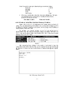
Managing GS-2224L through Ethernet Port
Before you communicate with the switch, you have to finish first the
configuration of the IP address or to know the IP address of the switch. Then,
follow the procedures listed below.
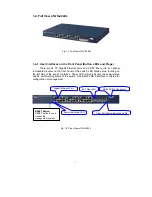
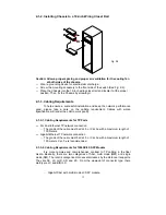
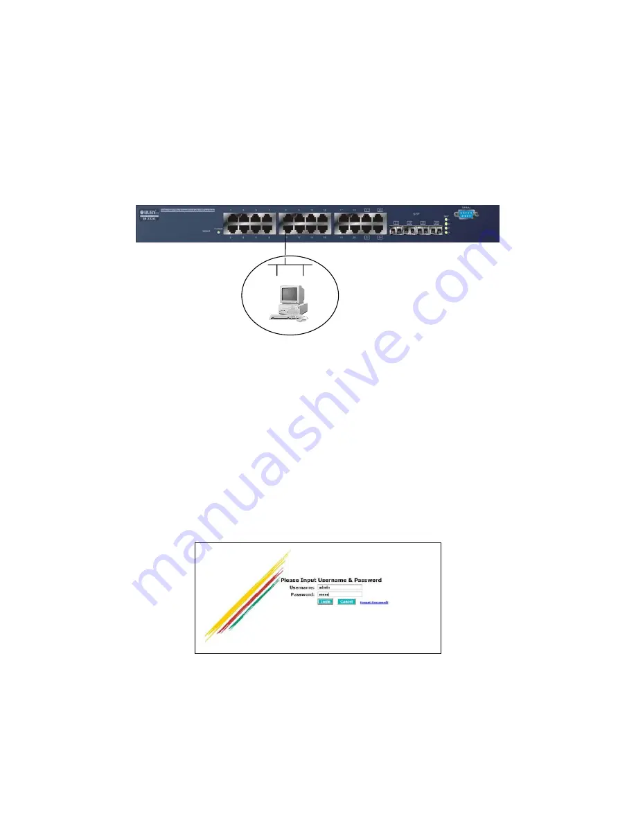
1. Set up a physical path between the configured the switch and a PC by a
qualified UTP Cat. 5 cable with RJ-45 connector.
Note: If PC directly connects to the switch, you have to setup the same
subnet mask between them. But, subnet mask may be different for the PC
in the remote site. Please refer to Fig. 2-9 about the switch’s default IP
address information.
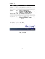
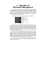
2. Run CLI or web browser and follow the menu. Please refer to Chapter 3
and Chapter 4.
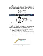
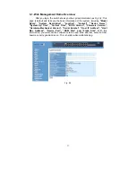
Fig. 2-10 the Login Screen for Web
GS-2224L L2 Managed Switch
Default IP Setting:
IP = 192.168.1.1
Subnet Mask = 255.255.255.0
Default Gateway = 192.168.1.254
Assign a reasonable IP address,
For example:
IP = 192.168.1.100
Subnet Mask = 255.255.255.0
Default Gateway = 192.168.1.254
Fig. 2-9
Ethernet LAN
Содержание GS-2224L
Страница 1: ......
Страница 2: ......
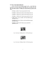
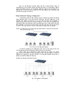
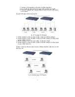
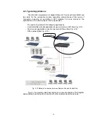
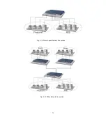
Страница 34: ...24 Fig 2 15 Office Network Connection Fig 2 14 Peer to peer Network Connection ...
Страница 78: ...68 Fig 3 28 ...
Страница 83: ...73 Fig 3 31 ...
Страница 91: ...81 Fig 3 39 Fig 3 40 Fig 3 41 ...
Страница 103: ...93 Fig 3 54 Set up Typical Network Application Rules Finish Fig 3 55 Set up Typical Network Application Rules Finish ...
Страница 113: ...103 Fig 3 67 Ingress Port Fig 3 68 ...
Страница 115: ...105 Fig 3 71 Fig 3 72 Fig 3 73 ARP Fig 3 74 ARP ...
Страница 116: ...106 Fig 3 75 ARP Fig 3 76 ARP Fig 3 77 ARP Fig 3 78 ARP ...
Страница 117: ...107 Fig 3 79 ARP Fig 3 80 ARP Fig 3 81 ARP Fig 3 82 ARP ...
Страница 118: ...108 Fig 3 83 ARP Fig 3 84 ARP Fig 3 85 ARP Fig 3 86 ARP Fig 3 87 ARP ...
Страница 119: ...109 Fig 3 88 IPv4 Fig 3 89 IPv4 Fig 3 90 IPv4 ...
Страница 120: ...110 Fig 3 91 IPv4 Fig 3 92 IPv4 Fig 3 93 IPv4 Fig 3 94 IPv4 Fig 3 95 IPv4 ...
Страница 121: ...111 Fig 3 96 IPv4 Fig 3 97 IPv4 Fig 3 98 IPv4 Fig 3 99 IPv4 Fig 3 100 IPv4 ...
Страница 122: ...112 Fig 3 101 IPv4 Fig 3 102 IPv4 Fig 3 103 IPv4 Fig 3 104 IPv4 ...
Страница 123: ...113 Fig 3 105 IPv4 Fig 3 106 IPv4 Fig 3 107 IPv4 ...
Страница 124: ...114 Fig 3 108 IPv4 Fig 3 109 IPv4 Fig 3 110 IPv4 Fig 3 111 IPv4 ...
Страница 125: ...115 Fig 3 112 IPv4 Fig 3 113 IPv4 Fig 3 114 IPv4 ...
Страница 126: ...116 Fig 3 115 IPv4 Fig 3 116 IPv4 Fig 3 117 IPv4 ...
Страница 127: ...117 Fig 3 118 Action Fig 3 119 Rate Limiter ...
Страница 128: ...118 Fig 3 120 Port Copy Fig 3 121 DMAC Filter ...
Страница 129: ...119 Fig 3 122 VLAN ID Filter Fig 3 123 VLAN ID Filter Fig 3 124 Tag Priority ...
Страница 141: ...131 Fig 3 126 Set up Policy Rules Fig 3 127 Set up Policy Rules Fig 3 128 Set up Policy Rules ...
Страница 142: ...132 Fig 3 129 Set up Policy Rules Finish Fig 3 130 Set up Port Policies Fig 3 131 Set up Port Policies ...
Страница 143: ...133 Fig 3 132 Set up Port Policies Fig 3 133 Set up Port Policies Finish ...
Страница 144: ...134 Fig 3 134 Set up Typical Network Application Rules Fig 3 135 Set up Typical Network Application Rules ...
Страница 150: ...140 Delete Select one of entry from the table then click on Delete to delete this entry Fig 3 143 ...
Страница 159: ...149 Fig 3 145 ...
Страница 204: ...194 Fig 4 1 Fig 4 2 ...


