ROZUM ROBOTICS
PULSE robotic arm
Page
18 | 23
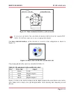
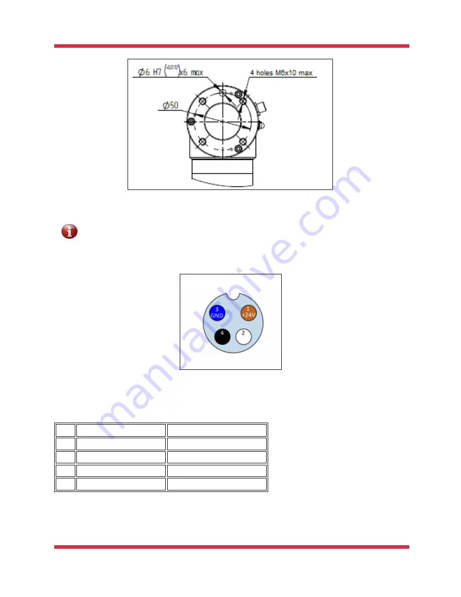
Figure 2-3: Basic mechanical interface on the arm wrist
In case your end effector has a mechanical interface different from the standard ISO
9409-1-50-4-M6 one, make sure to use an appropriate adaptor.
The
basic electrical interface
of the arm wrist is a socket of the configuration as shown in
Figure 2-4.
Figure 2-4: Basic electrical interface on the arm wrist
The pin assignment in the socket is as described in Table 2-3.
Table 2-3: Pin assignment in the end effector socket
Pin
Wire color
Signal
1
Brown
+24V
2
White
Digital output 1
3
Blue
GND
4
Black
Digital output 2
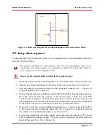
Figure 2-5 below is the electrical diagram for the digital outputs in the end effector socket on the
wrist. Make sure to observe the specified parameters when selecting and connecting an end
effector.


