


ROZUM ROBOTICS
PULSE robotic arm
Page
10 | 23
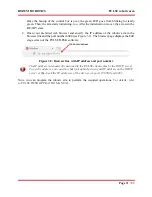
The back panel
On the back panel of the control box, you can find the following:
all major connectors of the robotic arm system
a power switch
a mains fuse
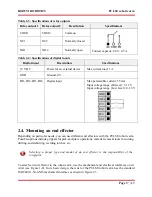
four holes for rack mounting
Figure 1-6: The back panel of the control box
No.
Intended use
1
4 digital inputs and 2 digital outputs (for details, see Section 2.3.3)
2
USB 2.0 port
3
mains fuse
4
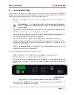
220V power cable connector
5
mains switch to switch on/ off power supply
6
Ethernet port for integrating the robotic arm into an enterprise network (for specifications,
see Table 1.4)
7
Connector for an emergency stop button
8
48V connector for the cable connecting the control box with the robotic arm
9
mounting holes
1.7. Emergency stop button
For the PULSE robotic arm, the emergency stop button is supplied as a standalone device pre-
assembled with a connection cable. The button is designed to provide Category 1 Stop in
accordance with ISO 10218-1—a controlled stop with power supplied to the servo motors in the
arm joints until full stop is achieved.


