Section 2 Installation
S7M / S8M Manual
www.rottlermfg.com
2-6
Installation Procedure
Location
The productivity of this machine will depend a great deal on it’s proper initial installation, particularly the
means by which cylinder blocks/heads are lifted into the machine as well as the material handling to and
from other operations in your shop.
The proper loading arrangement and location for your S7M & S8M machine is extremely important.
A slow travel (6 to 10 feet / min.) power hoist, operated from either a bridge crane or a jib crane
arrangement works very well. A 1000-lb. hoist is generally adequate for lifting the engine block. An air
hoist with speed control makes an ideal method for fast, convenient loading.
If some production surfacing with this machine is anticipated, and the cylinder blocks/heads are not
directly loaded and unloaded from a conveyor, we recommend considerable attention be given to the
crane so that it covers an adequate area to allow the operator to back up and remove cylinder blocks/
heads without cluttering up his own area. If two machines are to be operated by one operator, we
recommend that the open faces be placed at right angles to each other, with the machines about three
feet apart.
Unpacking
Use care in removing the crate from the S7M & S8M machine, do not use force on any part of the spindle
unit.
Remove the tool box, parallels, and optional tooling, located at the lower portion of the machine and
completely clean these articles, as well as the machine base pads and upper table, with solvent. Rust
inhibitor is applied to the machine at the time of shipment, any of this inhibitor left on the machine will
result in considerable collecting of cast iron dirt.
Shipping Hold Down Bolt
Remove cover (#7036E) from the rear of the spindle base by removing it’s four mounting screws. Remove
the bolt located in the front bottom of the spindle base. Replace the cover and tighten the four mounting
screws.
Leveling
Four square head set screws (502-1-12A), jam nuts (502-1-12F), and chamfered washer (502-1-12), are
provided with the machine for leveling. Insert the screw and nut at the base support points, being careful
that the screw point seats in the washer.
Use a precision level and level the upper table within .0005” per foot in both directions and make sure that
the machine weight is equally supported at the four support points of the base.
Air Supply
It is very important the air source for the S7M and S8M machine be moisture free.
Water and oil in
the line will result in early cylinder and valve failure.
Our recommendation is the installation of a water
trap at the machine.
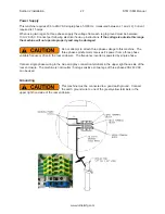
Attach a 100 PSI air source to the appropriate intake at the air filter on the side of the rear control
enclosure.
Содержание S7M
Страница 2: ......
Страница 4: ......
Страница 8: ...Section 1 Introduction S7M S8M Manual www rottlermfg com 1 4 ...
Страница 17: ...Section 2 Installation S7M S8M Manual www rottlermfg com 2 8 ...
Страница 18: ...Section 2 Installation S7M S8M Manual www rottlermfg com 2 9 ...
Страница 38: ...Section 5 Operating Instructions S7M S8M Manual www rottlermfg com 5 9 ...
Страница 42: ...Section 6 Maintenance S7M S8M Manual www rottlermfg com 6 2 S7M S8M Machine Lubrication Illustration ...
Страница 57: ...Section 6 Maintenance S7M S8M Manual www rottlermfg com 6 17 Pneumatic Control Diagram ...
Страница 65: ...Section 6 Maintenance S7M S8M Manual www rottlermfg com 6 25 Inner Spindle Lower Section Bearing Section View ...
Страница 66: ...Section 6 Maintenance S7M S8M Manual www rottlermfg com 6 26 ...
Страница 68: ...Section 7 Troubleshooting S7M S8M Manual www rottlermfg com 7 2 ...
Страница 70: ...Section 8 Machine Parts S7M S8M Manual www rottlermfg com 8 1 Machine Parts Front Right Side View S7 8M ...
Страница 71: ...Section 8 Machine Parts S7M S8M Manual www rottlermfg com 8 2 Pneumatic Assembly ...
Страница 72: ...Section 8 Machine Parts S7M S8M Manual www rottlermfg com 8 3 Electrical Enclosure ...
Страница 74: ...Section 8 Machine Parts S7M S8M Manual www rottlermfg com 8 5 Upper Housing ...
Страница 75: ...Section 8 Machine Parts S7M S8M Manual www rottlermfg com 8 6 Upper Vertical Travel Belt Parts ...
Страница 76: ...Section 8 Machine Parts S7M S8M Manual www rottlermfg com 8 7 Spindle Base Front Section ...
Страница 77: ...Section 8 Machine Parts S7M S8M Manual www rottlermfg com 8 8 Inner Outer Spindle Assembly ...
Страница 78: ...Section 8 Machine Parts S7M S8M Manual www rottlermfg com 8 9 Spindle Base Bushings ...
Страница 79: ...Section 8 Machine Parts S7M S8M Manual www rottlermfg com 8 10 Spindle Base Assembly ...
Страница 80: ...Section 8 Machine Parts S7M S8M Manual www rottlermfg com 8 11 Left Ballscrew Support ...
Страница 81: ...Section 8 Machine Parts S7M S8M Manual www rottlermfg com 8 12 Right Ballscrew Support ...
Страница 82: ...Section 8 Machine Parts S7M S8M Manual www rottlermfg com 8 13 Home and Limit Switches ...
Страница 83: ...Section 8 Machine Parts S7M S8M Manual www rottlermfg com 8 14 Pendant Assembly ...
Страница 84: ...Section 8 Machine Parts S7M S8M Manual www rottlermfg com 8 15 Spindle Base ...
Страница 85: ...Section 8 Machine Parts S7M S8M Manual www rottlermfg com 8 16 Chip Shield 14 16 ...
Страница 86: ...Section 8 Machine Parts S7M S8M Manual www rottlermfg com 8 17 14 Fly Cutter ...
Страница 87: ...Section 8 Machine Parts S7M S8M Manual www rottlermfg com 8 18 Chip Chute ...
Страница 88: ...Section 8 Machine Parts S7M S8M Manual www rottlermfg com 8 19 Waycovers and Optional Chip Catcher Assembly ...
Страница 89: ...Section 8 Machine Parts S7M S8M Manual www rottlermfg com 8 20 Riser Set ...
Страница 90: ...Section 8 Machine Parts S7M S8M Manual www rottlermfg com 8 21 Air Diagram ...
Страница 92: ...Section 9 Options S7M S8M Manual www rottlermfg com 9 2 ...
Страница 94: ...Section 10 Material Data Safety Sheets S7M S8M Manual www rottlermfg com 10 2 ...
Страница 95: ...Section 10 Material Data Safety Sheets S7M S8M Manual www rottlermfg com 10 3 ...
Страница 96: ...Section 10 Material Data Safety Sheets S7M S8M Manual www rottlermfg com 10 4 ...


