Section 6 Maintenance
S7M / S8M Manual
www.rottlermfg.com
6-4
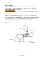
Setting Cutting Tool Inserts
Travel the spindle base approximately to the center of the main base.
Turn off all power to machine before proceeding.
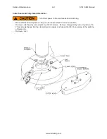
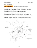
Remove vacuum housing from chip shield. Attach a dial runout indicator to a cylinder head or engine
block, etc.
Rotate cutter head and check to see that both inserts are the same distance from the center of the
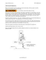
spindle, within .004. If adjustment is necessary loosen the tool holder clamp wedge, and the height
adjustment screw. Move tool in or out the required distance. Tighten the clamp wedge. Snug up the height
adjustment screw. There is a set screw located at the bottom of the toolholder, it locks a dowel pin in
place. When the in-out adjustment is set, loosen the set screw, the pin will pop out and hit the back of the
slot. Tighten the set screw. This way, when a tool holder is removed and then replaced, it will be located
very nearly where it was. Insert height will still need to be adjusted.
Rotate cutter head and check to see that both inserts are the same height within .0015-.0003. If
adjustment is necessary loosen the tool holder clamp wedge, then alternately loosen and tighten the
height adjusting screw and the retaining screw, until both inserts are set as desired. Retighten the tool
holder clamp wedge, and recheck both inserts.
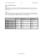
Production Cutting
Aluminum & Cast Iron
For fast tooling set-up, this machine can be set-up with one cast iron cutting insert and one aluminum
cutting insert. Set the cast iron insert with no down or out adjustment. Set the aluminum style insert .02
further out and .005 lower than the first insert. With the cutter head set up this way, aluminum work can
be easily cut. To cut cast iron simply remove the aluminum cutting insert from its holder.
Содержание S7M
Страница 2: ......
Страница 4: ......
Страница 8: ...Section 1 Introduction S7M S8M Manual www rottlermfg com 1 4 ...
Страница 17: ...Section 2 Installation S7M S8M Manual www rottlermfg com 2 8 ...
Страница 18: ...Section 2 Installation S7M S8M Manual www rottlermfg com 2 9 ...
Страница 38: ...Section 5 Operating Instructions S7M S8M Manual www rottlermfg com 5 9 ...
Страница 42: ...Section 6 Maintenance S7M S8M Manual www rottlermfg com 6 2 S7M S8M Machine Lubrication Illustration ...
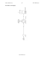
Страница 57: ...Section 6 Maintenance S7M S8M Manual www rottlermfg com 6 17 Pneumatic Control Diagram ...
Страница 65: ...Section 6 Maintenance S7M S8M Manual www rottlermfg com 6 25 Inner Spindle Lower Section Bearing Section View ...
Страница 66: ...Section 6 Maintenance S7M S8M Manual www rottlermfg com 6 26 ...
Страница 68: ...Section 7 Troubleshooting S7M S8M Manual www rottlermfg com 7 2 ...
Страница 70: ...Section 8 Machine Parts S7M S8M Manual www rottlermfg com 8 1 Machine Parts Front Right Side View S7 8M ...
Страница 71: ...Section 8 Machine Parts S7M S8M Manual www rottlermfg com 8 2 Pneumatic Assembly ...
Страница 72: ...Section 8 Machine Parts S7M S8M Manual www rottlermfg com 8 3 Electrical Enclosure ...
Страница 74: ...Section 8 Machine Parts S7M S8M Manual www rottlermfg com 8 5 Upper Housing ...
Страница 75: ...Section 8 Machine Parts S7M S8M Manual www rottlermfg com 8 6 Upper Vertical Travel Belt Parts ...
Страница 76: ...Section 8 Machine Parts S7M S8M Manual www rottlermfg com 8 7 Spindle Base Front Section ...
Страница 77: ...Section 8 Machine Parts S7M S8M Manual www rottlermfg com 8 8 Inner Outer Spindle Assembly ...
Страница 78: ...Section 8 Machine Parts S7M S8M Manual www rottlermfg com 8 9 Spindle Base Bushings ...
Страница 79: ...Section 8 Machine Parts S7M S8M Manual www rottlermfg com 8 10 Spindle Base Assembly ...
Страница 80: ...Section 8 Machine Parts S7M S8M Manual www rottlermfg com 8 11 Left Ballscrew Support ...
Страница 81: ...Section 8 Machine Parts S7M S8M Manual www rottlermfg com 8 12 Right Ballscrew Support ...
Страница 82: ...Section 8 Machine Parts S7M S8M Manual www rottlermfg com 8 13 Home and Limit Switches ...
Страница 83: ...Section 8 Machine Parts S7M S8M Manual www rottlermfg com 8 14 Pendant Assembly ...
Страница 84: ...Section 8 Machine Parts S7M S8M Manual www rottlermfg com 8 15 Spindle Base ...
Страница 85: ...Section 8 Machine Parts S7M S8M Manual www rottlermfg com 8 16 Chip Shield 14 16 ...
Страница 86: ...Section 8 Machine Parts S7M S8M Manual www rottlermfg com 8 17 14 Fly Cutter ...
Страница 87: ...Section 8 Machine Parts S7M S8M Manual www rottlermfg com 8 18 Chip Chute ...
Страница 88: ...Section 8 Machine Parts S7M S8M Manual www rottlermfg com 8 19 Waycovers and Optional Chip Catcher Assembly ...
Страница 89: ...Section 8 Machine Parts S7M S8M Manual www rottlermfg com 8 20 Riser Set ...
Страница 90: ...Section 8 Machine Parts S7M S8M Manual www rottlermfg com 8 21 Air Diagram ...
Страница 92: ...Section 9 Options S7M S8M Manual www rottlermfg com 9 2 ...
Страница 94: ...Section 10 Material Data Safety Sheets S7M S8M Manual www rottlermfg com 10 2 ...
Страница 95: ...Section 10 Material Data Safety Sheets S7M S8M Manual www rottlermfg com 10 3 ...
Страница 96: ...Section 10 Material Data Safety Sheets S7M S8M Manual www rottlermfg com 10 4 ...

