Section 4 Control Definitions
S7M / S8M Manual
www.rottlermfg.com
4-2
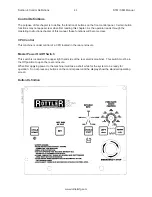
Emergency Stop
If the Emergency stop is pushed, all power to the spindle and horizontal drive is removed. Display will still
have power. To release the emergency stop, turn the button to the right and it will “POP” out. Give the
machine a minute to power up before pressing any buttons on the control panel.
Homing
When the machine is first powered up it needs to be homed. The left and right buttons flash. Press and
hold the Left and Right buttons for two (2) seconds. The machine will travel to the right at 50 inches per
minute to find the home sensor.
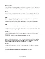
Right
This button has two functions. When pressed, and held the machine will travel to the right at 80” per
minute until the button is released or the right end of travel is reached.
If the spindle is on when this button is pressed, the machine will Feed to the right at the rate shown.
Travel will continue until the button is pressed again or the right end of travel is reached.
Left
This button has two functions. When pressed, and held, the machine will travel to the left at 80” per
minute until the button is released or the Left end of travel is reached.
If the spindle is on when this button is pressed, the machine will Feed to the left at the rate shown. Travel
will continue until the button is pressed again or the left end of travel is reached.
Spindle Start
This button will start the spindle at the speed shown. The spindle will continue to run until the button is
pressed again.
The spindle will not start if any of the rapid travel or cycle buttons are active.
End of Cut Set Button
This button is used to set the End of Cut position. When pressed the physical location of the cutterhead
will be the End of Cut position, more about the use of this button will be discussed later in this chapter
under Auto Cycle and again in the Operating Instructions chapter of this manual.
Feed Rate
The feed rate knob will change the feed rate. The available feed rate is from .004” to .040” per minute.
Spindle RPM
The Spindle RPM knob will change the RPM. The available RPM is 350 to 1200.
Содержание S7M
Страница 2: ......
Страница 4: ......
Страница 8: ...Section 1 Introduction S7M S8M Manual www rottlermfg com 1 4 ...
Страница 17: ...Section 2 Installation S7M S8M Manual www rottlermfg com 2 8 ...
Страница 18: ...Section 2 Installation S7M S8M Manual www rottlermfg com 2 9 ...
Страница 38: ...Section 5 Operating Instructions S7M S8M Manual www rottlermfg com 5 9 ...
Страница 42: ...Section 6 Maintenance S7M S8M Manual www rottlermfg com 6 2 S7M S8M Machine Lubrication Illustration ...
Страница 57: ...Section 6 Maintenance S7M S8M Manual www rottlermfg com 6 17 Pneumatic Control Diagram ...
Страница 65: ...Section 6 Maintenance S7M S8M Manual www rottlermfg com 6 25 Inner Spindle Lower Section Bearing Section View ...
Страница 66: ...Section 6 Maintenance S7M S8M Manual www rottlermfg com 6 26 ...
Страница 68: ...Section 7 Troubleshooting S7M S8M Manual www rottlermfg com 7 2 ...
Страница 70: ...Section 8 Machine Parts S7M S8M Manual www rottlermfg com 8 1 Machine Parts Front Right Side View S7 8M ...
Страница 71: ...Section 8 Machine Parts S7M S8M Manual www rottlermfg com 8 2 Pneumatic Assembly ...
Страница 72: ...Section 8 Machine Parts S7M S8M Manual www rottlermfg com 8 3 Electrical Enclosure ...
Страница 74: ...Section 8 Machine Parts S7M S8M Manual www rottlermfg com 8 5 Upper Housing ...
Страница 75: ...Section 8 Machine Parts S7M S8M Manual www rottlermfg com 8 6 Upper Vertical Travel Belt Parts ...
Страница 76: ...Section 8 Machine Parts S7M S8M Manual www rottlermfg com 8 7 Spindle Base Front Section ...
Страница 77: ...Section 8 Machine Parts S7M S8M Manual www rottlermfg com 8 8 Inner Outer Spindle Assembly ...
Страница 78: ...Section 8 Machine Parts S7M S8M Manual www rottlermfg com 8 9 Spindle Base Bushings ...
Страница 79: ...Section 8 Machine Parts S7M S8M Manual www rottlermfg com 8 10 Spindle Base Assembly ...
Страница 80: ...Section 8 Machine Parts S7M S8M Manual www rottlermfg com 8 11 Left Ballscrew Support ...
Страница 81: ...Section 8 Machine Parts S7M S8M Manual www rottlermfg com 8 12 Right Ballscrew Support ...
Страница 82: ...Section 8 Machine Parts S7M S8M Manual www rottlermfg com 8 13 Home and Limit Switches ...
Страница 83: ...Section 8 Machine Parts S7M S8M Manual www rottlermfg com 8 14 Pendant Assembly ...
Страница 84: ...Section 8 Machine Parts S7M S8M Manual www rottlermfg com 8 15 Spindle Base ...
Страница 85: ...Section 8 Machine Parts S7M S8M Manual www rottlermfg com 8 16 Chip Shield 14 16 ...
Страница 86: ...Section 8 Machine Parts S7M S8M Manual www rottlermfg com 8 17 14 Fly Cutter ...
Страница 87: ...Section 8 Machine Parts S7M S8M Manual www rottlermfg com 8 18 Chip Chute ...
Страница 88: ...Section 8 Machine Parts S7M S8M Manual www rottlermfg com 8 19 Waycovers and Optional Chip Catcher Assembly ...
Страница 89: ...Section 8 Machine Parts S7M S8M Manual www rottlermfg com 8 20 Riser Set ...
Страница 90: ...Section 8 Machine Parts S7M S8M Manual www rottlermfg com 8 21 Air Diagram ...
Страница 92: ...Section 9 Options S7M S8M Manual www rottlermfg com 9 2 ...
Страница 94: ...Section 10 Material Data Safety Sheets S7M S8M Manual www rottlermfg com 10 2 ...
Страница 95: ...Section 10 Material Data Safety Sheets S7M S8M Manual www rottlermfg com 10 3 ...
Страница 96: ...Section 10 Material Data Safety Sheets S7M S8M Manual www rottlermfg com 10 4 ...

