- 5 -
www.rotork.com www.remotecontrol.se
Adjustment of the Indicator Bridge
After the actuator has been mounted on the valve, the in
-
dicator bridge must be synchronized to the valve ends, not
only to get the latches to mesh and get indications of sig
-
nals, but also in order to prevent damages to the bridge.
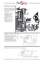
The actuator is normally delivered with the gear wheel
(3:S1/52) unmounted, see figure 6. If the actuator is
delivered mounted on a valve, the bridge mechanism and
indicating switches will be preset before dispatch.
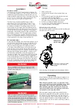
Figure 7
3:S1/41
3:S1/9-10
3:S1/14
4
3
2
1
Figure 6
3:S1/52
3:S1/7-8
Indicator Bridges 175S, 100S and 050S
These indicator bridges will be delivered without the
screw (3:S1/31), and the bridge turned so that the bridge
gears (3:S1/48 and GDS1:1+GDD2:1/5) do not mesh.
The bridge is fastened by screws in place, after the valve
is closed entirely and the instructions given for the types
175, 100 and 050 above have been carefully observed.
The actuator is now synchronized to the valve. Should the
actuator ever be removed from the valve, synchronization
must be checked after re-installation.
The bridge is just an indicating and control device and is
not intended to ”stall out” the actuator.
Indicator bridge 175, 100 and 050
1. Remove the cover.
2. Close the valve entirely.
3. Undo the two stops No. 1 & 2 closed to the slide block
(3:S1/9-10), so that it can move freely within the whole
range. Figure 6 shows the adjustment of the stops.
Damage could occur if the slide block runs against the
stops 1 & 2 moving them more than 3,2 mm.
4. Make sure that the slide block stands close to the
bracket (3:S1/14), so that there is space enough on
bridge spindle for valve to open, figure 7.
5. Bring over the shaft (3:S1/41) about 3 mm against
bracket (3:S1/14), so that the latch (3:S1/26) figure 2,
is turned in a suitable position to grasp the catch
(2:S1/12). Suitable tool: Seeger circlip pliers.
6. Bring the stop No.1 between the slide block and the
bracket (3:S1/14) towards the slide block and screw on
tightly.
7. Put the bridge gear (3:S1/52) in place.
8. Open the valve entirely, and check that the slide block
can move freely within the whole range, figure 3 shows
the slide-block (3:S1/9-10) in open valve position.
9. Bring over the shaft (3:S1/41) in the opposite direction
(about 3 mm) and fasten the stop No.2 by screws after
having been brought towards the slide block.
10. Adjust the other two stops, (3 & 4), so that the micro-
switches are actuated at the end positions of the valve.
11. Fit the cover and tighten the screws.
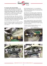
Risk for injuries caused by crushing/squeezing and
electrical shocks when the actuator is energized by air
pressure and electricity with its cover off. Before open
-
ing, check that the compressed air and possible power
supply are disconnected. The cover should be mounted
when the actuator operates.
WARNING!


